ATTACHMENT OPERATOR’S MANUAL 36” Rotary Tiller 36” Rotary Tiller Attachment (for use with Conquest / 1700 / 2700, Prestige / 1800 / 2800 & Snapper YT400 and GT500 Series Garden Tractors) Mfg. No. 1695419 1694151 Description 36” Tiller 36” Tiller CAUTION: Read and follow all instructions. Manual Part No. 1723861 Revision 04 Rev.
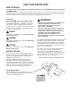
SAVE THESE INSTRUCTIONS READ THE MANUAL The operator’s manual contains important safety information you need to be aware of BEFORE you operate your unit as well as DURING operation. Safe operating techniques, an explanation of the product’s features and controls, and maintenance information is included to help you get the most out of your equipment investment.
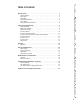
Safery Table of Contents Setup & Installation Operator Safety . . . . . . . . . . . . . . . . . . . . . . . . . . . . . . . . . . . . . . . . . . 2 Read the Manual . . . . . . . . . . . . . . . . . . . . . . . . . . . . . . . . . . . . . . . . . . . . . 2 Safety Icons . . . . . . . . . . . . . . . . . . . . . . . . . . . . . . . . . . . . . . . . . . . . . . . . . 2 Safety Risks . . . . . . . . . . . . . . . . . . . . . . . . . . . . . . . . . . . . . . . . . . . . . . . . . 2 Identification Numbers. . .
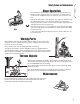
Safery Safety Rules & Information Operating Safety Congratulations on purchasing a superior-quality piece of lawn and garden equipment. Our products are designed and manufactured to meet or exceed all industry standards for safety. Power equipment is only as safe as the operator. If it is misused, or not properly maintained, it can be dangerous! Remember, you are responsible for your safety and that of those around you. Use common sense, and think through what you are doing.
Safety Rules and Information Safery Slope Operation You could be seriously injured or even killed if you use this unit on too steep an incline. Using the unit on a slope that is too steep or where you don’t have adequate traction can cause you to lose control or roll over. A good rule of thumb is to not operate on any slope you cannot back up (in 2-wheel drive mode). You should not operate on inclines with a slope greater than a 3.5 foot rise over a 20 foot length.
Safety Rules & Information Safery This machine is capable to amputating hands and feet and throwing objects. Read these safety rules and follow them closely. Failure to obey these rules could result in loss of control of unit, severe personal injury or death to you, or bystanders, or damage to property or equipment. The triangle in text signifies important cautions or warnings which must be followed. TRAINING OPERATION 1.
Safety Rules and Information CHILDREN SERVICE, MAINTENANCE, AND STORAGE 1. Check shear bolts and other bolts at frequent intervals for proper tightness to be sure the equipment is in safe working condition. 2. Always refer to the operator’s manual for important details if the tiller is to be stored for an extended period. 4. Maintain or replace safety and instruction labels as necessary. 5. Maintain or replace safety and instruction labels as necessary. 6.
Initial Setup & Installation INITIAL INSTALLATION Note: Recommended Accessories Setup & Installation Rear wheel weights and front counterweights are recommended. For operation on slopes greater than 15% (8.5°), front counterweights are required. Never operate on slopes greater than 17.6% (10°). Initial Installation Notes: • The tiller idler pulley is wired to the tiller for shipping purposes. USE CAUTION WHEN CUTTING THE WIRE - THE IDLER ARM IS UNDER SPRING TENSION.
Initial Setup & Installation M Setup & Installation J L A A J K K I I H H B B C C D D E E G F Figure 3. Lift Components - Mowing A. Clevis Pin B. 5/15-18 x 1 Capscrew (Gr. 5) C. Washer D. Lift Link (Original) E. Lift Lock F. Lift Lever G. Locknut H. Hair Pin Clip I. Spacer J. Lift Cam K. Mower Hole F G Figure 4. Lift Components - Tilling A. Clevis Pin B. 5/16-18 x 1 Capscrew (Gr. 5) C. Washer D. Lift Link (New) E. Lift Lock F. Lift Lever G. Locknut H. Hair Pin Clip I. Spacer J.
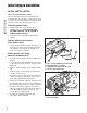
Initial Setup & Installation Setup & Installation Install the Hitches 1. Install the lower drawbar hitch (F, Figure 5) on the outside of the rear frame wrapper (E) and the hitch support (C) on the inside. Secure both to the rear frame wrapper (E) using two 5/16-18 x 1-1/4 capscrews (G) and two 5/16-18 nylock nuts (A). D E C 2. Secure the bottom of the lower hitch (F) to the drawbar using two 1/2-13 x 1-1/2 capscrews (H), washers (I), and two 1/2-13 nylock nuts (J). B 3.
Initial Setup & Installation Install the Pulley Assemblies 1. Install the rear pulley assembly (D, Figure 7) into the left side of the rear hitch (C). Secure the bottom of the pulley assembly to the lower drawbar hitch (A) with pin (B). Setup & Installation D C Figure 9. Front Idler Pulley Installed Install the Rear Idler Pulley Assembly (Select Models) B 1.
Initial Setup & Installation Setup & Installation A D B C Figure 11. Lift Linkage Installation A. Turn Crank B. Clevis Pin and Safety Clip C. Lift Rod D. Front Bracket Install the Lift Rod 1. Connect the rear of the lift rod (C, Figure 11) to the upper hitch. Secure with a clevis pin (B) and safety clip. 2. Slide the lift bracket (A, Figure 12) and lift rod assembly on the right stub at the end of the lift assembly cross-shaft. Secure with a clevis pin and hair pin clip (see Figure 12 inset).
Initial Setup & Installation Install the Tiller B A 1. Position the tiller at the rear hitch and insert the lift bar (A, Figure 13) into the upper hitch (B). Secure with a clevis pin and safety clip. Setup & Installation 2. Rotate the tiller upward so that the hitch arms (C) are aligned with the lower hitch (D). Secure with two clevis pins and safety clips. D C Figure 13. Tiller Installation A. Lift Bar B. Upper Hitch C. Hitch Arm D. Lower Hitch E D F F B A Figure 14.
Operation OPERATION NOTICE Refer to the Tractor Operator’s Manual for important information concerning safely operating your tractor. CAUTION After striking a foreign object, stop the engine, disengage the PTO, and remove the key. Inspect the tiller for damage before starting. The tiller may propel the tractor forward when first lowered into hard ground especially if tiller depth is set too deep or tractor ground speed is too fast. Checks Before Starting Operation 1.
Storage & Maintenance STORAGE Daily Storage Long Term Storage Note: Refer to the tractor Operator’s Manual for important information concerning safely storing your tractor. 1. Use water pressure or brush to thoroughly clean the unit. 1. Allow tractor engine to cool before storing in any enclosure. 2. After jobs are completed, hose or brush down the unit to remove dirt and debris. 3. Lightly grease or oil all pivot points. Coat bare metal surfaces to prevent corrosion. MAINTENANCE WARNING 3.
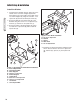
Removal & Normal Installation REMOVAL 1. Remove the belt from the spring-loaded tiller idler pulley (D, Figure 15). E 2. Remove the belt from the PTO pulley (A, Figure 14). 3. Remove the front pulley assembly (B). 4. Remove the pin (B, Figure 16) securing the rear pulley assembly. D 5. Raise the tiller. C B 6. Manual Lift Models: Release the tension on the lift assist spring (A, Figure 17). Remove the threaded rod spring (B) from the front bracket. A 7. Lower the tiller. 8.
Removal & Normal Installation B A A B C Figure 17. Lift Assist Spring A. Spring B. Threaded Rod Spring C. Lift Rod D C Figure 19. Tiller Assembly A. Lift Bar B. Upper Hitch C. Hitch Arm D. Lower Hitch A C Removal & Installation D Figure 18. Lift Arm Extension A. Lift Bracket A B Figure 20. Lift Link Positions-Normal A. Clevis Pin B. Spacer and Hair Pin Clip C. Mowing Position D.
Troubleshooting, Adjustments, & Service TROUBLESHOOTING WARNING Troubleshooting procedures are provided in the following chart. To use these procedures, first locate the problem description that best describes the trouble that you have encountered. Check the possible causes one at a time in the order that they are listed. Correct any problems that are found and try to operate the rotary tiller again to see if you have eliminated the trouble.
Troubleshooting, Adjustments, & Service LIFT HEIGHT ADJUSTMENT (MANUAL LIFT MODELS) INITIAL ADJUSTMENT 1. Park the unit on level ground. 2. Turn the lift spring assist crank (A, Figure 24) until the length of threaded rod between the bracket and end of the threaded rod spring (B) and the bracket measures 6”. Note: Lubricate the crank and threaded rod with oil. 5" 3. Fully raise the tiller. 4. Adjust the rear lift rod nuts (B, Figure 23) until the bottom tines ar 5” above the ground. 5.
Hardware Identification & Torque Specifications Common Hardware Types Torque Specification Chart Hex Head Capscrew FOR STANDARD MACHINE HARDWARE (Tolerance ± 20%) Washer Hardware Grade Lockwasher Carriage Bolt No Marks SAE Grade 2 Hex Nut Size Of Hardware Standard Hardware Sizing 8-32 8-36 10-24 10-32 1/4-20 1/4-28 5/16-18 5/16-24 3/8-16 3/8-24 7/16-14 7/16-20 1/2-13 1/2-20 9/16-12 9/16-18 5/8-11 5/8-18 3/4-10 3/4-16 7/8-9 7/8-14 1-8 1-12 When a washer or nut is identified as 1/2”, this is the
NOTES Notes 21
www.simplicitymfg.com www.MasseyLawn.com www.snapper.com www.AGCOLawn.com Briggs & Stratton Power Products Group, L.L.C. Copyright © 2008 Briggs & Stratton Corporation Milwaukee, WI USA. All Rights Reserved www.BRIGGSandSTRATTON.