ATTACHMENT OPERATOR’S MANUAL Clean Sweep Triple Catcher Clean Sweep Triple Catcher Mfg. No. 1695169 Description Clean Sweep Triple Catcher 1733866 Rev. 04 Rev.
THIS PAGE INTENTIONALLY BLANK (FOR PLACEMENT ONLY - DO NOT PRINT)
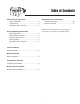
Table of Contents Safety Rules & Information General Warnings............................................2 Safety Decals ..................................................2 Storing the Grass Catcher ...............................3 Normal Removal & Installation Collector Installation ......................................10 Collector Removal .........................................11 NOTE: In these instructions, “left” and “right” are referred to as seen from the operating position.
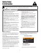
Safety Rules & Information Read these safety rules and follow them closely. Failure to obey these rules could result in loss of control of unit, severe personal injury or death to you, or bystanders, or damage to property or equipment. The triangle in text signifies important cautions or warnings which must be followed. GENERAL WARNINGS • If the mower stalls or the collector chute plugs: 1. Disengage the PTO; 2. Stop the engine and remove the key; 3.
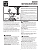
General Operating Instructions Before Operation Clear the lawn of all sticks, stones, wire and other debris which may be caught or thrown by the mower blades. Check grass condition. If wet, wait until later in the day. If grass is wet, the grass catcher is likely to become plugged. For efficient bagging, air circulation under the mower deck, through the chute and into the bag is very important.
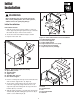
Initial Installation B F WARNING Before beginning any service work turn off the PTO, set the parking brake, turn off the ignition, and disconnect the spark plug wire(s). D C Initial Installation C A HITCH INSTALLATION 1. Slide the 5/16-18 speed nut (A, Figure 1) onto rear frame support (E) through square hole (C) so that the threaded side (B) is on the inside of tractor. D E 2. Secure the 5/16-18 shoulder bolt (D) as shown. 3. Repeat on the other side. Figure 2.
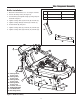
Tube Component Assembly Baffle Installation 1. Determine which baffle to use. See Figure 4 Chart. 44” Mower Deck 50” Mower Deck 2. Lift side discharge chute (H, Figure 4). “A” RH side 26-1/4” long RH side 29-3/4” long 3. Insert baffle (F) through discharge opening and position baffle into place. “B” LH side 24-7/8” long LH side 27-3/4” long 4. Tighten carriage bolts (A) and nuts (E) on baffle (F). 5. Tighten carriage bolt (B) and nut (E) on baffle (F). 6. Position baffle (G) into place. 7.
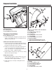
Component Installation C B A D A C E F B G G H J Figure 5. Install Mounting Plate A. Mounting Plate B. Locknuts, 5/16-18 C. Carriage Bolts, 5/16-18 x 5/8 I Figure 6. Lower Chute to Boot Installation A. Pin, Latch B. Carriage Bolt, 1/4-20 x 5/8 C. Locknut, 1/4-20 D. Lower Chute E. Locknut, Center Lock, 5/16-18 F. Strap, Rubber G. Locknuts, Whiz Lock, 5/16-18 H. Rod, Boot Mount I. Capscrew, Hex Head, 5/16-18 x 1-1/4 J.
Install Upright Support & Bag Support Bracket INSTALL UPRIGHT SUPPORT TO HITCH INSTALL BAG AND COVER SUPPORT 1. Install the upright support (B, Figure 8) to hitch (A) and secure with 3/8-16 x 1 capscrews (C) and locknuts (D) as shown. 1. Install the bag and cover support (B, Figure 9) to upright support (A) using reinforcement plate (C) and 3/8-16 x 1 capscrews (D) and 3/8-16locknuts (E) as shown. B B E D C A C D A Figure 8. Install Upright Support A. Hitch B. Upright Support C.
Cover and Bag Installation INSTALL COVER ASSEMBLY INSTALL COLLECTOR BAGS 1. Attach cover assembly (B, Figure 10) to bag support bracket (A) using hinge pivots (E). Secure cover using cover hinge pins (C) and hair pins (D) as shown. 1. Raise the cover (A, Figure 11). 2. Attach collector bags (B) using grass bag hanger (C) to bag hanger post (D). Note: It may be necessary to fold seat forward to allow cover to stay in the raised position. A C B D D E C A B D E Figure 11.
Tube Installation D C D C E B A B A Figure 13. Install Upper Tube to Cover A. Upper Tube B. Cover C. Ridge, Upper Tube D. Ridge Cutout Figure 12. Install Lower Tube A. Lower Chute Rod B. Mounting Plate C. Rubber Strap D. Discharge Deflector E. Locknut 44” Frame Hung Mowers 50” Frame Hung Mowers 44” Free Floating Mowers LOWER TUBE INSTALLATION 1. Lift discharge deflector up (D, Figure 12). 50” Free Floating Mowers 2. Insert lower chute rod (A) into mounting plate (B). 3.
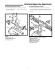
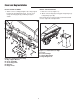
Normal Removal & Installation E F R Q D G C A D C B P H O N I J K M A. B. C. D. E. F. G. H. I. Hitch Support Assembly Cover Pin Hair Pins Bag Grass Bag Hanger Upper Tube Middle Tube Strap, Boot J. Deflector K. Nut & Capscrew L. Mounting plate M. Lower Chute Rod N. Lower Chute O. Pin P. Strap, Middle Q. Ridge R. Ridge Cutout L Figure 15. Normal Installation & Removal Normal Removal & Installation 4. Lift discharge deflector (J) up. Insert lower chute rod (M) into mounting plate (L).
Normal Removal Collector Removal WARNING OPERATION WITHOUT BAGGER For operation without bagger, the mower deflector MUST be properly installed in the down position and retained by the spring latch. 1. Unhook strap (P, Figure 15) from pin (O). Slide middle tube (H) into upper tube (G) and remove middle tube (H). Remove upper tube (G) from cover (B). 2. Lift up cover (B) remove and empty bags (E). 3. Unhook strap (I) from locknut and capscrew (K). Remove lower chute (N) from mounting plate (L).
MANUFACTURING, INC. Simplicity Mfg. Inc.500 N Spring Street / PO Box 997 Port Washington, WI 53074-0997 Simplicity Mfg. Inc.500 N Spring Street / PO Box 997 Port Washington, WI 53074-0997 www.AGCOLawn.com www.SimplicityMfg.com Simplicity Mfg. Inc. - Snapper Products 535 Macon Street McDonough, GA 30253 Simplicity Mfg. Inc.500 N Spring Street / PO Box 997 Port Washington, WI 53074-0997 www.Snapper.com www.MasseyLawn.