ATTACHMENT OPERATOR’S MANUAL Snow/Dozer Blade & Hitch Snow Plow/Dozer Blade Mfg. No. 1693754 Description 42” Remote Angling Snow Plow/Dozer Blade Hitch Mfg. No.
Table of Contents Maintenance & Normal Care Schedule..............6 Schedule for Normal Care ...............................6 Lubricate the Dozer Blade ...............................6 Recommended Accessories ..............................1 Safety Rules & Information General Warnings............................................2 Operating on Slopes........................................2 Preparation ......................................................2 Operating Safety....................................
Safety Rules & Information Read these safety rules and follow them closely. Failure to obey these rules could result in loss of control of unit, severe personal injury or death to you, or bystanders, or damage to property or equipment. The triangle in text signifies important cautions or warnings which must be followed. PREPARATION GENERAL WARNINGS ● Disengage the PTO before making any adjustments. ● Never attempt to make any adjustments while engine is running.
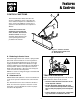
Features & Controls CONTROL FUNCTIONS A The information below briefly describes the function of individual controls. Operating the tractor and dozer require the combined use of these controls and additional controls whose operation is described in the tractor Operator’s Manual. B Please take a moment and familiarize yourself with the name, location, and function of these controls so that you will better understand the safety and operating instructions provided in this manual. Figure 1.
General Operating Instructions Checks Before Starting WARNING 1. Refer to the Maintenance & Adjustments sections of this manual and perform any needed service. Also, refer to the tractor Operator’s Manual and perform any required service. Perform the Safety System Interlock test found in your tractor Operator’s Manual. If tractor does not pass the test, do not operate the tractor. See your authorized dealer. Under no circumstances should you attempt to defeat the safety system. 2.
General Operating Instructions Changing Angle of the Blade: Snow Plowing Tips See Figure 1 for location of Controls. • Determine the best snow removal pattern before beginning. NOTE: It is easier to change the angle of the blade with the attachment raised. • Plan the pattern so that you avoid pushing snow onto cleared areas. 1. Raise the attachment lift. • When land contour permits, it is best to travel in the longest direction to minimize turning. 2.
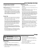
Maintenance WARNING Lubricate Dozer Blade To avoid serious injury, perform maintenance on the tractor or dozer blade only when the engine is stopped, parking brake is set and all moving parts have stopped. Always remove the ignition key before beginning maintenance or adjustments to prevent accidental starting of the engine. Lubricate the dozer blade as shown in Figure 2. Where an oil can is shown, wipe the area clean, apply a few drops of oil (SAE 30), then wipe up drips or spills.
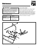
Adjustments Skid Shoe Adjustment Slotted holes are provided to permit adjustment of the shoe assemblies for raising and lowering the blade to various working heights (see Figure 3). When cleaning snow from gravel or earth drives or walks, the shoe assemblies should be lowered fully to prevent blade contact with gravel or ground. When cleaning smooth hard surfaces like concrete, the shoe assemblies are normally placed fully up to allow the blade to scrape the surface.
Adjustments Lift Rod Adjustment In the fully raised position the blade should be 6” off the ground. In the fully lowered position, the lift rod should slightly compress the spring creating downward pressure on the blade. D C B NOTE: Always adjust the lift height before and after adjusting the downward pressure. A IMPORTANT NOTE DO NOT OVER-COMPRESS THE SPRINGS. In addition to providing downward pressure, the springs are an elastic medium that absorbs shocks caused by bumps and cracks in ground surfaces.
Initial Setup & Assembly 1 4 5 4 6 3 4 2 4 3 7 8 9 10 29 28 11 12 27 2 26 25 22 24 23 10 21 20 17 18 19 15 13 15 14 16 Figure 7.
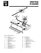
Initial Setup & Assembly 2 8 1 7 3 4 5 3 19 6 18 16 21 12 4 16 14 13 20 18 8 9 8 17 15 9 11 10 8 Figure 8. Push Bar, Hitch, & Lift Rod Components Ref Qty 1 2 2 2 3 2 4 2 5 1 6 1 7 1 8 5 9 2 10 1 11 1 Description STOP, Bar SCREW, Taptite, 5/16-18 x 1 SETSCREWS, 5/16 x 1/2 SET COLLAR ROD GUIDE ASSY.
Initial Setup & Assembly Figure 9. Bar Stop A. Bar Stops B. Taptite Screws, 5/16-18 x 1 Figure 10. Tension Springs A. Eyebolt D. Pivot Frame B. Nut, 5/16 E. Nut, 5/16 C. Spring INITIAL SETUP & ASSEMBLY NOTE: Some of the following setup procedures may already be completed. Assemble Blade 1. Place the blade on a flat surface. 2. Install the bar stops (A, Figure 9) using the two 5/1618 x 1 taptite screws (B). 3. See Figure 10.
Initial Setup & Assembly Assemble Lift Rod D 1. Assemble lift rod per Figure 11. Lift Rod Adjustment C Different types of terrain may require an adjustment to the lift rod assembly. For instructions on how to make this adjustment refer to the “Lift Rod Adjustment” procedure in the ADJUSTMENTS section of this manual. B A Figure 11. Lift Rod Assembly A. Set Collars C. Spring B. Rod Guide D. Lift Rod Install Blade 1. Drive the tractor over the push bar until rear of push bar is under front hitch. 2.
Initial Setup & Assembly Install Angling Control Rod NOTE: If installing the dozer attachment on a unit equipped with a snowcab, replace the control rod support (A, Figure 13) with the hanging support (Ref. No. 19, Figure 8). Mount the hanging support to the front cab cross-bar. A B 1. Set the angling control support (A, Figure 13) against the right side of the frame. Insert two 5/16-18 x 1-1/2 capscrews (C) through the support (A), and frame.
Attaching & Removing A B D C B Figure 15. Dozer Removal A. Support Arm C. Pivot Pin B. Hair Pin Clip D. Hair Pin Clip & Washer E C E. Clevis Pins REMOVAL & INSTALLATION Removing & Attaching Dozer Blade 1. Lower the blade. 4. Remove the pivot pin (C) connecting the blade and pushbar. Remove the blade. 2. Remove the hair pin clip and washer (D, Figure 15) securing the angling control rod to the clevis. Disconnect the angling control rod. 5. Remove pin (E) securing hitch to the tractor. 8.
Hardware Identification & Torque Specifications Common Hardware Types Torque Specification Chart Hex Head Capscrew FOR STANDARD MACHINE HARDWARE (Tolerance ± 20%) Washer Hardware Grade Lockwasher Carriage Bolt No Marks SAE Grade 2 Hex Nut Size Of Hardware Standard Hardware Sizing 8-32 8-36 10-24 10-32 1/4-20 1/4-28 5/16-18 5/16-24 3/8-16 3/8-24 7/16-14 7/16-20 1/2-13 1/2-20 9/16-12 9/16-18 5/8-11 5/8-18 3/4-10 3/4-16 7/8-9 7/8-14 1-8 1-12 When a washer or nut is identified as 1/2”, this is the N
NOTES 16
MANUFACTURING, INC. 500 N Spring Street / PO Box 997 Port Washington, WI 53074-0997 www.simplicitymfg.com © Copyright 2000 Simplicity Manufacturing, Inc. All Rights Reserved. Printed in USA.