ATTACHMENT OPERATOR’S MANUAL Turbo Clean Sweep Twin Catcher Turbo Clean Sweep Twin Catcher Mfg. No.
Table of Contents Safety Rules & Information General Warnings............................................2 Safety Decals ..................................................2 Catcher Assembly - All Models Assemble Supports & Hitch.............................5 Install Cover & Bags ........................................6 Assemble & Install Tubes ................................6 General Operating Information Mowing with the Triple Catcher........................3 Recommended Accessories....................
Safety Rules & Information Read these safety rules and follow them closely. Failure to obey these rules could result in loss of control of unit, severe personal injury or death to you, or bystanders, or damage to property or equipment. The triangle in text signifies important cautions or warnings which must be followed. GENERAL WARNINGS • Know the unit’s controls and how to stop quickly. READ THE OPERATOR’S MANUALS. • Read and obey all safety decals.
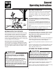
General Operating Instructions BEFORE OPERATION Clear the lawn of all sticks, stones, wire and other debris which may be caught or thrown by the mower blades. Check grass condition. If wet, wait until later in the day. If grass is wet, the grass catcher is likely to become plugged. For efficient bagging, air circulation under the mower deck, through the chute and into the bag is very important.
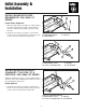
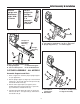
Initial Assembly & Installation INSTALL MOUNTING PLATES BROADMOOR / 1600 / 2600 / LT SERIES A B C Install Plates & Spacers 1. Mount the side brackets (B, Figure 1) to both sides of the frame using the holes shown. Secure with one 3/8-16 x 1 capscrew (C) and 3/8-16 nylock nut (A) per side. 2. Install the rear spacers (C, Figure 2). Secure with two 1/2-13 x 2-1/2 capscrews (E), washers (D), spacers (C), and 1/2-13 nylock nuts (A) per side. Figure 1. Install Side Brackets A. Nylock Nut, 3/8-16 C.
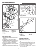
Initial Assembly & Installation Use this upright with Broadmoor / 1600 / 2600 / LT Series Use this upright with Prestige / 1800 / 2800 / YT & Conquest / 1700 / 2700 / GT Series C B Figure 4. Upright Identification D A A Conquest & Broadmoor Mounting Holes Figure 6. Assemble Catcher Frame (Prestige Shown) A. 3/8-16 Nut & Lockwasher C. 3/8-16 x 1 Capscrews B. Upright Support Assy. D. Lower Support D Prestige Mounting Holes B A C Figure 5. Assemble Catcher Frame A. Upright Support C.
Initial Assembly & Installation A B C A B C D Figure 9. Install Cable A. Cable B. Support E C. Washer E G F F D C H I B A Figure 8. Install Catcher (Prestige Shown) A. #10-32 Nut F. Bags B. Handle G. Hair Pin Clip C. #10-32 x 1/2 Screw H. Catcher Hitch D. Cover I. Spacers E. Hinge Pin Figure 10. Install Tubes A. Flange Nut B. Clip C. #10-32 x 1/2 Screw & Washer D. Lower Tube E. #10-32 Nut & Washer F. Upper Tube Install Cover and Bags 1.
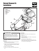
Normal Removal & Installation A. B. C. D. E. F. G. Tubes Hair Pin Clip Frame Spacers Bags Clevis Pin Cover Clip F A E G D B C Figure 11. Normal Removal & Installation (Prestige Shown) WARNING Installation 1. Mount the catcher frame on the frame spacers (C, Figure 11). OPERATION WITHOUT TURBO & CATCHER For operation without turbo, the mower deflector MUST be properly installed in the down position and retained by the spring latch (see turbo operator’s manual). 2. Install the bags (D). 3.
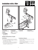
Installation with a Tiller C B I H A D G F A B C D E Figure 13. Installation (Prestige Shown) A. Tiller Hitch C. Hair Pin Clip B. Clevis Pin D. Support Assembly Figure 12. Initial Setup (Prestige Shown) A. Nuts, 5/16-18 G. Carriage Bolts, B. Lockwashers, 5/16 3/8-16 x 3/4 C. Plate H. Nuts & Lockwashers, D. Spacers 3/8 E. Lower Support I. Upright Support F.
Notes 9
Hardware Identification & Torque Specifications Common Hardware Types Torque Specification Chart Hex Head Capscrew FOR STANDARD MACHINE HARDWARE (Tolerance ± 20%) Washer Hardware Grade Lockwasher Carriage Bolt No Marks SAE Grade 2 Hex Nut Size Of Hardware Standard Hardware Sizing 8-32 8-36 10-24 10-32 1/4-20 1/4-28 5/16-18 5/16-24 3/8-16 3/8-24 7/16-14 7/16-20 1/2-13 1/2-20 9/16-12 9/16-18 5/8-11 5/8-18 3/4-10 3/4-16 7/8-9 7/8-14 1-8 1-12 When a washer or nut is identified as 1/2”, this is the N
MANUFACTURING, INC. 500 N Spring Street / PO Box 997 Port Washington, WI 53074-0997 www.simplicitymfg.com © Copyright 2005 Simplicity Manufacturing, Inc. All Rights Reserved. Printed in USA.