ATTACHMENT OPERATOR’S MANUAL Wide Body Cart Grass Catcher Wide Body Cart Grass Catcher Mfg. No. 1694542 Description Wide Body Cart Grass Catcher (Multiple Applications) 1726564 Revision 01 Rev.
Table of Contents Contents, Accessories, & Specs Table of Contents.............................................1 Recommended Accessories............................1 Specifications ..................................................1 Initial Assembly & Installation Cart Assembly .................................................8 Cover Assembly...............................................9 Normal Installation & Removal Installation .....................................................11 Removal............
Safety Rules & Information Read these safety rules and follow them closely. Failure to obey these rules could result in loss of control of unit, severe personal injury or death to you, or bystanders, or damage to property or equipment. The triangle in text signifies important cautions or warnings which must be followed. GENERAL WARNINGS • • • • • • • • • • • •Know the unit’s controls and how to stop quickly. READ THE OPERATOR’S MANUALS. Read and obey all safety decals.
General Operating Instructions BEFORE OPERATION Clear the lawn of all sticks, stones, wire and other debris which may be caught or thrown by the mower blades. Check grass condition. If wet, wait until later in the day. If grass is wet, the grass catcher is likely to become plugged. For efficient bagging, air circulation under the mower deck, through the chute and into the bag is very important.
Operation OPERATION Dumping Grass and Leaves 1. Back the tractor to the desired place for unloading. Shut the tractor's engine of before getting off the tractor's seat. WARNING Before opening the cover for any reason, engage the parking brake, shut off the engine, remove the key, and wait for all moving parts to stop. Figure 1. Opening the Cover 2. Unhook the strap from the door lock and raise the cover assembly to the open position.
Notes 5
Exploded View Diagrams No. 1 2 3 4 5 6 7 8 9 10 11 12 13 14 15 16 2 1 37 13 13 36 39 3 17 35 4 18 19 20 5 17 6 21 15 7 9 10 8 38 11 19 17 14 16 14 19 12 30 34 33 18 19 6 32 22 21 23 31 22 23 24 25 26 27 28 29 20 6 30 31 32 33 34 35 36 37 38 39 12 29 24 27 28 28 25 26 Figure 3. Wide Body Dump Cart 6 Qty.
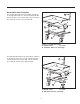
Reversible Frame Orientation A For Left Side discharge locate the handle (A, Figure 4) on the right side of the cart. Use the U-bracket (B) with the hole located 1-1/2” from the edge. Rotate the frame (C) so that the offset is on the left hand side. 1-1/2” B Offset C Figure 4. Left Side Discharge A. Handle, Latch C. Frame B. U-Bracket, Hole 1-1/2” from edge For Right Side discharge locate the handle (A, Figure 5) on the left side of the cart.
Initial Assembly & Installation B A B A A Figure 6. Wheel Assembly (RH Dishcarge Shown) A. Wheel Assembly B. Frame CART ASSEMBLY Figure 7. Install U-Bracket A. U-Bracket B. Box 1. Determine if you have a right side or left side discharge. Refer to Figures 4 & 5. 2. Install the wheel assemblies (A, Figure 6) to the frame (B). Place the head of the swivel wheel on the end of the frame. Align the holes and place four 3/816 x 1 hex bolts up through the frame and head of the swivel.
Initial Installation & Assembly B A A Figure 11. Install Frame Rod A. Opening B. Frame Rod Figure 10. Install Support Tube A. Support Tube A 6. Install support tube (A, Figure 10) inside the box. Align each end of the support tube with the two holes at the front corner side of the box. Place one 5/16-18 x 1-1/2 hex bolt with a 5/16 flat washer and plastic spacer through the top, outside hole of the box and the support tube. Secure with a 5/16 locknut on the inside.
Initial Assembly & Installation E C B D A A Figure 15. Install Connecting Sleeve A. Connecting Sleeve B. Support Tube C. Sleeve Clamp D. Truss Head Screw, 1/4-20 x 1/2 E. Nyloc Nut Figure 16. Install Straight Rod A. Straight Rod C 6. Install the sleeve clamp (C, Figure 15) to the connecting sleeve (A) with 1/4-20 x 1/2 slotted truss head screw (D) and nyloc nut (E). Install the connecting sleeve inside the collar of the cover and position sleeve clamp (C) over the support tube (B). A B 7.
Normal Removal & Installation NORMAL INSTALLATION & REMOVAL C Installation B 1. Insert the upper end of the clear tube into the cart sleeve. Slide the flex hose (C, Figure 20) over the turbo (A) and secure with the large hose clamp (B). The hose should overlap the turbo discharge by 2”3”. A The clamp screw should be positioned to the inside as shown to prevent accidental impact and removal of the clamp. Check that the upper end of the clear tube is not contacting the top of the collector cover.
Hardware Identification & Torque Specifications Common Hardware Types Torque Specification Chart Hex Head Capscrew FOR STANDARD MACHINE HARDWARE (Tolerance ± 20%) Washer Hardware Grade Lockwasher Carriage Bolt No Marks SAE Grade 2 Hex Nut Size Of Hardware Standard Hardware Sizing 8-32 8-36 10-24 10-32 1/4-20 1/4-28 5/16-18 5/16-24 3/8-16 3/8-24 7/16-14 7/16-20 1/2-13 1/2-20 9/16-12 9/16-18 5/8-11 5/8-18 3/4-10 3/4-16 7/8-9 7/8-14 1-8 1-12 When a washer or nut is identified as 1/2”, this is the N
MANUFACTURING, INC. 500 N Spring Street / PO Box 997 Port Washington, WI 53074-0997 www.simplicitymfg.com © Copyright 2004 Simplicity Manufacturing, Inc. All Rights Reserved. Printed in USA.