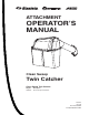
ATTACHMENT OPERATOR’S MANUAL Clean Sweep Twin Catcher Clean Sweep Twin Catcher Mfg. No. 1695163 Description Clean Sweep Twin Catcher 1733419 Rev. 00 Rev.
Table of Contents Safety Rules & Information General Warnings............................................2 Safety Decals ..................................................2 General Operating Instructions Before Operation .............................................3 Mowing with the Catcher .................................3 After Operation ................................................3 Storing the Grass Catcher ...............................3 Initial Installation Hitch Installation ...................
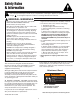
Safety Rules & Information Read these safety rules and follow them closely. Failure to obey these rules could result in loss of control of unit, severe personal injury or death to you, or bystanders, or damage to property or equipment. The triangle in text signifies important cautions or warnings which must be followed. GENERAL WARNINGS • Know the unit’s controls and how to stop quickly. READ THE OPERATOR’S MANUALS. • Read and obey all safety decals.
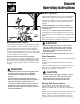
General Operating Instructions Before Operation Clear the lawn of all sticks, stones, wire and other debris which may be caught or thrown by the mower blades. Check grass condition. If wet, wait until later in the day. If grass is wet, the grass catcher is likely to become plugged. For efficient bagging, air circulation under the mower deck, through the chute and into the bag is very important.
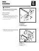
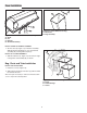
Initial Installation WARNING Before beginning any service work turn off the PTO, set the parking brake, turn off the ignition, and disconnect the spark plug wire(s). B A Initial Installation Hitch Installation A 1. Slide the 5/16-18 speed nut (A, Figure 1) onto rear frame support (E) through square hole (C) so that the threaded side (B) is on the inside of tractor. C E 2. Secure the 5/16-18 shoulder bolt (D) as shown. D 3. Repeat on the other side. Figure 1. Install Spacer (left side shown) A.
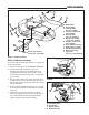
Baffle Installation C B F A. Baffle (New) B. Spacer (New) C. Carriage Bolts, 5/16-18 x 2 (New) D. Locknuts, WHIZ Lock, 5/16-18 (New) E. Carriage Bolt, 5/16-18 x 5/8 (New) F. Wing Nut Assembly, Large, 5/16-18 (New) G. Locknut, Center Lock, 5/16-18 (New) H. Grass Shield (Existing) I. Blade, High Lift (New) J. Hex Washer (Existing) K. Washer (Existing) L. Capscrew, 7/16-14 x 1-1/4 (Existing) D G H I J E A D K L Torque Capscrew to 45-55 ft. lbs. (61-75 Nm) Figure 3.
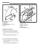
Puck Installation C D A C B A D E F F G E F D G Figure 6. Install Pin and Bracket A. Lower Chute B. Locknut, 1/4-20 C. Puck, Metal D. Capscrews, Thin Head, 5/16-18 x 3/4 E. Locknuts, 5/16-18 F. Bracket Figure 7. Install Latch & Hinge to Cover Assembly A. Cover Assembly B. Latch C. Locknuts, ESNA, #10-24 D. Screws, #10-24 x 5/8 E. Hinge F. Locknuts, 1/4-20 G. Screw, Slotted, 1/4-20 x 1/2 Component Installation BRACKET AND PIN INSTALLATION ON LOWER CHUTE 1.
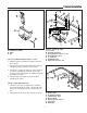
Channel Installation C E C A G F C D B D D C F B A D Figure 9. Install “U” Tube A. “U” Tube B. Channel Assembly C. Carriage Bolts, 5/16-18 x 1-3/4 D. Nuts, Nylock, 5/16-18 E. “L” Channel F. Saddle Brackets G. Capscrew, 5/16-18 x 3/4 Figure 8. Install Channel Assembly A. Channel Assembly B. Hitch C. Pin INSTALL CHANNEL ASSEMBLY AND “U”-TUBE 1. Slide the channel assembly (A, Figure 8) into hitch (B) as shown. 2.
Cover Installation A B C A Figure 12. Install White Bar to Bag A. White Bar B. Bag Assembly D B Figure 11. Install Cover to Channel Assembly A. Cover B. Pin C. Hair Pin D. Channel Assembly INSTALL COVER TO CHANNEL ASSEMBLY 1. Set the cover (A, Figure 11) on channel assembly. Slide pin (B) through hinge on cover and channel assembly (D) securing with hair pin (C). A INSTALL CLIP TO BAG ASSEMBLY 1. Slide the white bar (A, Figure 12) onto smooth edge of bag frame and assembly (B) as shown.
Install Latch & Hinge LOWER DISCHARGE CHUTE INSTALLATION A 1. Lift discharge deflector up (D, Figure 14). 2. Slide the notch of bracket (G) on to deflector hinge rod (F). G 3. Secure the front of lower chute (A) to carriage bolt (D) using wing nut (B). E F Note: Locknut (C) is intended to keep wing nut (B) permanently on carriage bolt (D). B C D CONNECTING DISCHARGE TUBE 1. Slide discharge tube (B, Figure 15) into seal (C).
Normal Removal & Installation Normal Removal & Installation A Collector Installation Note: See previous pages for more detailed installation and operation instructions if necessary. G 1. Lift discharge deflector up (E, Figure 16). E F 2. Slide the notch of bracket (G) on to deflector hinge rod (F). B 3. Secure the front of lower chute (A) to carriage bolt (D) using wing nut (B). C D 4. Mount the the channel assembly (A, Figure 17) into hitch (D).
Normal Removal F E L G J A B C H K I D A. B. C. D. E. F. Channel Assembly Cover Pin Hitch Bag White Bar G. Tubes H. Boot I. Puck J. Discharge Tube K. Wire Form L. Seal Figure 17. Normal Installation & Removal Collector Removal 4. Lift discharge deflector up (E, Figure 16). 5. Loosen wing nut (B). WARNING 6. Slide lower chute (A) off carriage bolt (D) and deflector hinge rod (F).
MANUFACTURING, INC. Simplicity Mfg. Inc. 500 N Spring Street / PO Box 997 Port Washington, WI 53074-0997 Simplicity Mfg. Inc. 500 N Spring Street / PO Box 997 Port Washington, WI 53074-0997 www.AGCOLawn.com www.SimplicityMfg.com Simplicity Mfg. Inc. 500 N Spring Street / PO Box 997 Port Washington, WI 53074-0997 www.MasseyLawn.com © Copyright 2006 Simplicity Manufacturing, Inc. All Rights Reserved. Printed in USA.