Safety Instruction & Operators Manual for SNAPPER MODEL 211SST TRIMMER Thank you for buying a Snapper Product! Before operating your trimmer, read this manual carefully and pay particular attention to the Important Safety Instructions on page two. Remember that trimmers and all power equipment can be dangerous If used improperly and keep in mind that safety requires careful use in accordance with the instructions and -.common sense! GENERAL SPECIFICATIONS TYPE IDLE (DECLAMATORY . CLUTCH ENGAGE RPM. .
IMPORTANT SAFETY INSTRUCTIONS WARNING: Failure to comply with the hollowing Instructions may result in serous Injury to the operator or other persons. The owner of the trimmer must understand these Instructions and, furthermore, must allow only persons who understand these instructions to operate the unit. Each person operating the trimmer must be of sound mind and body and must not be under the Influence of any substance which might impair vision, dexterity, or judgment.
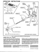
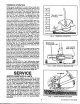
OPERATING INSTRUCTION TOOL KIT NO. 4-3980 ADJUSTABLE HANDLE DRIVE SHAFT HOUSING GEAR HOUSING {PAGE 7) LINE LIMITER (PAGE 8) BUMP-N-FEED TWIN LINE HEAD (PAGE & 7) FIG. LOCATION OF CONTROLS & OTHER FEATURES PREMIX FUEL (32 to 1 RATIO) For proper lubrication, the engine must operate on an exact mixture of gasoline and 2 cycle air-cooed engine oll. Use mixture. Use a good quality regular grade leaded or unleaded gasoline and SNAPPER special formulated 2-cycle engine oil. Do not use the special 50:1 ratio oils.
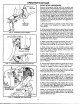
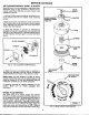
OPERATION (Continued) STOP BUTTON THROTTLE TRIGGER FIG. 2 CONTROLS ON HANDLE td YA AIR CLEANER Ci N\ TICKLER VALVE PRIMER BULB IDLE MIXTURE ADJUSTMENT employer FIG. 4 CARBURETOR CONTROLS START-STOP PROCEDURE Become thoroughly familiar with the location and function of all controls before operating the trimmer, Be prepared to stop quickly in the event of an emergency-stop the engine by pushing and holding the red push bunion on the inclined handle down until the engine stops.
TRIMMING OPERATION When using the Modal 211.in the trimmer mode with the BUMP-N-FEED head installed, keep each end of the twin line not less than 3 inches away from the outer edge of the head. This would produce an approximate cutting path of 10-1/2 inches. The line can be extended to a maximum of 8-3/4 inches to produce an 18” path, however, if extended more than this, the ends of the line will be clipped off by the Sine cutting bide which is part of the debris shield.
SERVICE (Continued) AIR CLEANER-SERVICE EVERY 25 HOURS Every 25 hours, or more frequently if operating under extremely dusty or dirty conditions, service.the air cleaner as follows. Replace any parts found to be damaged (Figure 8). 1. Use the Phillips head screwdriver provided in tool kit to remove the two air cleaner cover retaining Screws, 2. Remove the cover. The element, holder and screen will normally stay inside the recess in the air cleaner cover.
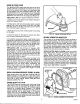
BUMP-N-FEED HEAD The BUMP-N-FEED head does not have to be completely removed to replenish the trimming line. New line can be wound on the spool or a new spool can be purchased with line installed. Make sure .095” mono filament line is used. Use the correct Snapper replacement line or spool DO NOT use substitutes, especially wire which can be dangerous (Figure 9), REPLENISH LINE with engine stopped as follows: 1. Place unit on work bench with weight resting on shield and engine stand. 2.
SERVICE (Continued) FUEL SYSTEM SERVICE An all.position diaphragm type carburetor is used on the 2181ST, The'carburetor has fixed main jet but has adjustable idle speed and idle mixture adjustments. Do not tamper with these adjustments. If the engine wail not stat, stalls at die or stalls under rapid acceleration, and the cause is not due to the air cleaner or muffler, or fouled plug readjust the carburetor diastolic: Refer to figure 4 for adjustment points (Page 4). . 1.