Safety Instructions & Operator's Manual for 21" STEEL DECK WALK MOWERS SERIES 12 & 14 MODELS PUSH MODELS 215012 215014 R215012 N215012 NR215012 FR215012 FR215014 PROPELLED MODELS P216012 EP216012 NP216012 RP215012 RP216012 RP215012T2 FRP216012 NRP215012 NFRP216012 MODEL NUMBER EXPLANATION I RI MODEL DESIGNATION SELF-PROPELLED CUTTING WIDTH.
IMPORTANT SAFETY INSTRUCTIONS WARNING: This powerful cutting machine is capable of amputating hands and feet and can throw objects that can cause injury and damage! Failure to comply with the following SAFETY instructions could result in serious injury or death to the operator or other persons. The owner of the machine must understand these instructions and must allow only persons who understand these instructions to operate machine.
IMPORTANT SAFETY INSTRUCTIONS OPERATION MAINTENANCE 1. 1. 2. 3. 4. 5. 6. 7. 8. 9. 10. 11. 12. 13. 14. 15. DO NOT put hands or feet near or under rotating parts. Keep clear of discharge area while engine is running. STOP engine when crossing gravel drives, walks, or roads, and under any conditions where thrown objects might be a hazard. Mow only in daylight or good artificial light. DO NOT operate mower while under the influence of alcohol or drugs.
TABLE IMPORTANT SAFETY TABLE OF CONTENTS OF CONTENTS INSTRUCTIONS ............................................. 2 & 3 ............................................................................ 4 SECTION 1 - FAMILIARIZATION SECTION 2 - OPERATING .............................................................. INSTRUCTIONS 5 ......................................... 6-8 Pre-start Checklist ...............................................................................................
Section 1 - FAMILIARIZATION ENGINE SPEED CONTROL GROUND SPEED CONTROL--[ ENGINE SPEED DECALS FAST "FAST" i CONTROL SLOW I I "SLOW" i SPEED CONTROL BLADE CONTROLRELEASE TO STOP E AND ENGINE HANDLE \ _--ROPESTART HANDLE DRIVE CONTROLRELEASE TO STOP FORWARD MOTION _OPESTARTMOUNTEDON RIGHTSIDEOFHANDLE) GRASS BAG CONNECTOR HANDLE PRIMER BAG AND LOWER HANDLE RE_ ADJUSTMENT BULB FILL CAP DIPSTICK FILLER CAP DECK LATCH "IGHT ADJUSTMENT LATCH CATCHER MODEL SHOWN (ROPE START MOUNTED ON LEFT SI
Section 2 - OPERATING 2.1 INSTRUCTIONS PRE-START CHECK LIST Make the following checks and perform the service required before each start-up. 2.1.1. Check guards, deflectors, grass bag, adapter and covers to make sure all are in place and securely tightened. 2.1.2. Check blade control and wheel drive control to insure they work freely. See Figure 2.1. f RECYCLING 2.1.6. Clean exterior surfaces of cutting deck and engine of any accumulation of spilled fuel, dirt, grass, oil, etc.
Section 2 - OPERATING INSTRUCTIONS 2.2.2. PROPELLING MOWER (Self Propelled Models Only) 1. Move ground speed control to the desired speed position. See Figure 2.4. 2. Start engine. Refer to Section "Starting & Operation". 3. Move wheel drive control against handle to engage wheel drive and propel mower forward. Forward speed can be adjusted while the mower is moving by changing position of the ground speed control. See Figure 2.4.
Section 2 - OPERATING INSTRUCTIONS WARNING service engineany andmaintenance, blade running.adjustments STOP engine DO NOTwith attempt or and blade. Disconnect spark plug wire and secure away from spark plug. Engine and components are HOT. Avoid serious burns, allow sufficient time for all components to cool. _._.-% 2.7 NOTE: Under certain conditions, when mulching, some grass may blow out from under front of baffle. This is normal but, the amount of grass blowing out can be reduced.
Section 3 - MAINTENANCE 3.1 3.2 INTRODUCTION To retain the quality of the mower, use genuine SNAPPER replacement parts only. Contact a local SNAPPER dealer for parts and service assistance. For the correct part or information for a particular mower, always mention model and serial number. SERVICE - AFTER FIRST 5 HOURS 3.2.1. CHANGE ENGINE OIL 3.2.2. CHECK GREASE LEVEL IN TRANSMISSION 1. Remove transmission fill plug• Roll machine forward or backward while looking down into plug hole. 2.
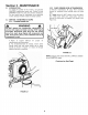
Section 3- MAINTENANCE 3.2.2. CHECK GREASE LEVEL IN TRANSMISSION 3.2.4 (Continued from previous page) CHECK ENGINE DRIVE BELT 1. Visually check engine drive belt for cracking, fraying, severed or belt strands exposed. If worn or damaged, replace belt before operating mower. NOTE: Do not spill grease or oil on surface of drive disc. See Figure 3.3. 3. Reinstall transmission plug. 4. Check grease level after each 25 hours of operation. 3.2.5 CHECK TRANSMISSION POLY-V BELT 1.
Section 4 - REPAIR & ADJUSTMENTS _IL 2. Replace the blade if it is badly chipped, bent, noticeably out of balance or has cracks or notch in either tip. See Figure 4.1 & 4.1A. Replace with new blade. WARNING DO NOT attempt any maintenance, adjustments or service with engine and blade running. STOP engine and blade. Disconnect spark plug wire and secure away from spark plug. Engine and components are HOT. Avoid serious burns, allow sufficient time for all components to cool.
Section 4 - REPAIR & ADJUSTMENTS WARNING CLUTCH CABLE VINYL SPRING DO NOT attempt any maintenance, adjustments or service with engine and blade running. STOP engine and blade. Disconnect spark plug wire and secure away from spark plug. Engine and components are HOT. Avoid serious burns, allow sufficient time for all components to cool. CLUTCH CABLE UPPER HOOK SPRI 4. Sharpen blade on a grinding wheel at an angle of 22 to 28 degrees. DO NOT sharpen blade beyond original cutting edge. See Figure 4.4.
Section 4 - REPAIR & ADJUSTMENTS WARNING USE \ DO NOT attempt any maintenance, adjustments or service with engine and blade running. STOP engine and blade. Disconnect spark plug wire and secure away from spark plug. Engine and components are HOT. Avoid serious burns, allow sufficient time for all components to cool. 4.3 \ DRIVEN DISC SERVICE If the mower does not propel itself properly, See Figure 4.6.
Section 4 - REPAIR & ADJUSTMENTS WARNING 1/8" MEASUREMENT DO NOT attempt any maintenance, adjustments or service with engine and blade running. STOP engine and blade. Disconnect spark plug wire and secure away from spark plug. Engine and components are HOT. Avoid serious burns, allow sufficient time for all components to cool. 4.3.3. TO DISC DRIVE DISC SLIDE DRIVEN DISC ASSEMBLY TOWARD OUTSIDE EDGE \ DRIVEN DISC ADJUSTMENT (Continued From Previous Page) 2.
Section 4 - REPAIR & ADJUSTMENTS 4.3.5. Replacing Bearing In Driven Disc Assembly If the driven disc bearing fails, remove the driven disc assembly and replace bearing as follows: 1. Using a small flat blade screwdriver, free the clip from the transfer rod. Then remove the transfer rod from the clip and the speed control rod. See Figure 4.11. 2. Using needle nose pliers, unhook the drive spring and slide the driven disc assembly off the hex shaft. See Figure 4.12. 3.
Section 4 - REPAIR & ADJUSTMENTS 4.4.1. Engine Drive Belt Replacement 1. Empty the fuel tank. 2. Unhook the idler spring from the right rear wheel bracket. See Figures 4.16. WARNING DO NOT attempt any maintenance, adjustments or service with engine and blade running. STOP engine and blade. Disconnect spark plug wire and secure away from spark plug. Engine and components are HOT. Avoid serious burns, allow sufficient time for all components to cool. RIGHT REAR WHEEL BRACKET IDLER SPRING IDLER SLOT IN 4.
Section 4 - REPAIR & ADJUSTMENTS WARNING DO NOT attempt any maintenance, adjustments or service with engine and blade running. STOP engine and blade. Disconnect spark plug wire and secure away from spark plug. Engine and components are HOT. Avoid serious burns, allow sufficient time for all components to cool. SPRING RIGHT WHEEL BRACKET 4.4.1. Engine Drive Belt Replacement (Continued from Previous Page) 5.
TROUBLESHOOTING PROBLEM PROBABLE CAUSE CORRECTIVE ACTION Fill fuel tank with fresh fuel. Engine Will Not Start 1• Fuel tank empty• 1, Using Recoil Starter 2. Engine needs choking or priming• 2. Choke/Prime. Check Engine Manual for Instructions. 3. Place spark plug wire onto spark plug. Spark plug wire disconnected. 1 • Blade control is released or is not being held securely against handle. 2, Choke control in the "CHOKE" position. 3• Fuel tank empty.
SERVICE SCHEDULE ITEM SERVICE PERFORMED Engine Oil Air Pre-Cleaner REF. Check Oil Level Page 6 Initial Oil Change Page 9 Periodic Oil Change Page 10 Clean Sponge Element EACH USE Spark Plug Replace Engine Manual.
® 3 YEAR LIMITED WARRANTY For three (3) years from purchase date for the original purchaser's residential, non-commercial use, SNAPPER, through any authorized SNAPPER dealer will replace, free of charge (except for taxes where applicable), any part or parts found upon examination by the factory at McDonough, Georgia, to be defective in material or workmanship or both.
PRIMARY MAINTENANCE an illustration of how dirt can ge your engine & how reasonable maintenance can protect it! Snapper uses the best avail) able engines and components In their products in order to provide long, satisfactory ._ service. However, proper • care is essential In ;" prolonging engine life.
PRIMARY MAINTENANCE g that dirt will quickly ruin an engine, manufacturers equip their engines with extremely efficient air cleaners to the harmful di_. The engine must gulp about 12,001] gallons of air for _f its working ment, the air avai to your Snapper eng heavily saturated with airborne dirt particles. As the dirt particles are stopped, they build up and begin to clog the outside of the filter.
PRIMARY MAINTENANCE • ; • Air Is also needed to keep your engine cool. Dirt, dust & debris build up to restrict and clog cooling air Intake screens and fins. Clean screens and fins at frequent Intervals. The engine blower housing and shrouds should be removed at least once each season or more often t under dry, dusty conditions for a thorough cleaning of Dirt can also be Introduced into an engine In dirty fuel from a contaminated container.
PRIMARY MAINTENANCE On 2-cycle engines, lubrication must be provided by an exact mixture of gasoline and 2-cycle air-cooled engine oil A 2-cycle engine that Is mistakenly run on straight gasoline will be ruined in less than 5 minutesl If you keep straight gasoline In addition to pre-mixed 2-cycle engine fuel, be sure the containers are clearly marked to avoid mix-up.
NOTES 25
NOTES 26
NOTES 27
Safety Instructions & Operator's Manual for P ® 21" STEEL DECK WALK BEHIND MOWERS SERIES 12 & 14 IMPORTANT Snapper products are built using engines that meet or exceed all applicable emissions requirements on the date manufactured. The labels on those engines contain very important emissions information and critical safety warnings. Read, Understand, and Follow all warnings and instructions in this manual, the engine manual, and on the machine, engine and attachments.