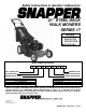
Safety Instructions & Operator’s Manual for 21” STEEL DECK WALK MOWERS SERIES 17 MODELS 2167517BV P2167517BV P2167517BVE WP2167517BV MODEL NUMBER EXPLANATION P SELF-PROPELLED CUTTING WIDTH ENGINE HORSE POWER W – Model Designation P – Self Propelled Model 21 – 21” Cutting Width 675 – 6.
IMPORTANT SAFETY INSTRUCTIONS WARNING: This powerful cutting machine is capable of amputating hands and feet and can throw objects that can cause injury and damage! Failure to comply with the following SAFETY instructions could result in serious injury or death to the operator or other persons. The owner of the machine must understand these instructions and must allow only persons who understand these instructions to operate machine.
IMPORTANT SAFETY INSTRUCTIONS OPERATION MAINTENANCE AND STORAGE 1. DO NOT put hands or feet near or under rotating parts. Keep clear of discharge area while engine is running. 2. STOP engine when crossing gravel drives, walks, or roads, and under any conditions where thrown objects might be a hazard. 3. Mow only in daylight or good artificial light. 4. DO NOT operate mower while under the influence of alcohol or drugs. 5.
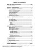
TABLE OF CONTENTS IMPORTANT SAFETY INSTRUCTIONS.............................................2 & 3 TABLE OF CONTENTS ............................................................................ 4 SECTION 1 - FAMILIARIZATION.............................................................. 5 SECTION 2 - OPERATING INSTRUCTIONS......................................... 6-9 Pre-start Checklist ...............................................................................................
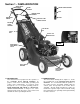
Section 1 - FAMILIARIZATION WHEEL DRIVE CONTROL BLADE CONTROL ENGINE SPEED CONTROL FAST GROUND SPEED CONTROL SLOW ROPE START HANDLE ELECTRIC START IGNITION SWITCH ENGINE SPEED CONTROL FUEL FILLER CAP GRASS BAG OIL FILL CAP AND DIPSTICK ENGINE PRIMER REAR HEIGHT ADJUSTMENT LATCH GRASS BAG ADAPTER FRONT HEIGHT ADJUSTMENT LATCHES FIGURE 1.1 1.1 INTRODUCTION This manual has been prepared for the operators of the SNAPPER WALK BEHIND MOWERS.
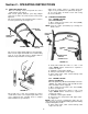
Section 2 - OPERATING INSTRUCTIONS 2.1 PRE-START CHECK LIST Make the following checks and perform the service required before each start-up. 2.1.1. Check guards, deflectors, grass bag, adapter and covers to make sure all are in place and securely tightened. 2.1.2. Check blade control and wheel drive control to insure they work freely. See Figure 2.1. 2.1.6. Clean exterior surfaces of cutting deck and engine of any accumulation of spilled fuel, dirt, grass, oil, etc.
Section 2 - OPERATING INSTRUCTIONS 2.2.3. PROPELLING MOWER (Self Propelled Models Only) 1. Start engine. Refer to Section “Starting & Operation”. 2. Move ground speed control to the desired speed position. See Figure 2.4. 3. Move wheel drive control against handle to engage wheel drive and propel mower forward. Forward speed can be adjusted while the mower is moving by changing position of the ground speed control. See Figure 2.4. 2.
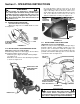
Section 2 - OPERATING INSTRUCTIONS 2.8 INSTALLATION of RECYCLING PLUG (Optional Accessory on Some Models) STEP 1: Once adapter has been installed, recycling may be desired. Insert recycling plug completely and securely into adapter. Install grass bag. See Figure 2.9. WARNING DO NOT attempt any maintenance, adjustments or service with engine and blade running. STOP engine and blade. Disconnect spark plug wire and secure away from spark plug. Engine and components are HOT.
Section 2 - OPERATING INSTRUCTIONS C. Install discharge deflector and secure to deck using hardware just removed in Step A. Slot in front edge of discharge deflector must be under nut as shown and both bolts protruding through holes in the side of the deflector. Secure nuts to the side of deflector. Tighten nuts securely. See Figure 2.13. WARNING DO NOT attempt any maintenance, adjustments or service with engine and blade running. STOP engine and blade.
Section 3 – MAINTENANCE 3.1 INTRODUCTION To retain the quality of the mower, use genuine SNAPPER replacement parts only. Contact a local SNAPPER dealer for parts and service assistance. For the correct part or information for a particular mower, always mention model and serial number. 3.2.2. CHECK GREASE LEVEL IN TRANSMISSION 1. Remove transmission fill plug. Roll machine forward or backward while looking down into plug hole. 2.
Section 3 – MAINTENANCE 3.2.4. CHECK ENGINE DRIVE BELT 1. Visually check engine drive belt for cracking, fraying, severed or belt strands exposed. If worn or damaged, replace belt before operating mower. 3.2.2. CHECK GREASE LEVEL IN TRANSMISSION (Continued from previous page) NOTE: Do not spill grease or oil on surface of drive disc. See Figure 3.3. 3. Reinstall transmission plug. 4. Check grease level after each 25 hours of operation. 3.2.5. CHECK TRANSMISSION POLY-V BELT 1.
Section 4 - REPAIR & ADJUSTMENTS 2. Replace the blade if it is badly chipped, bent, noticeably out of balance or has cracks or notch in either tip. See Figure 4.1 & 4.1A. Replace with new blade. WARNING DO NOT attempt any maintenance, adjustments or service with engine and blade running. STOP engine and blade. Disconnect spark plug wire and secure away from spark plug. Engine and components are HOT. Avoid serious burns, allow sufficient time for all components to cool.
Section 4 - REPAIR & ADJUSTMENTS WARNING CLUTCH CABLE DO NOT attempt any maintenance, adjustments or service with engine and blade running. STOP engine and blade. Disconnect spark plug wire and secure away from spark plug. Engine and components are HOT. Avoid serious burns, allow sufficient time for all components to cool. VINYL SPRING 1/16” TO 1/8” CLEARANCE UPPER SPRING CLUTCH CABLE EYE SPRING HOOK LOWER SPRING 4. Sharpen blade on a grinding wheel at an angle of 22 to 28 degrees.
Section 4 - REPAIR & ADJUSTMENTS USE NEEDLE NOSE PLIERS TO INSTALL DRIVE SPRING WARNING DO NOT attempt any maintenance, adjustments or service with engine and blade running. STOP engine and blade. Disconnect spark plug wire and secure away from spark plug. Engine and components are HOT. Avoid serious burns, allow sufficient time for all components to cool. 4.3 DRIVEN AND DRIVE DISC SERVICE If the mower does not propel itself properly, See Figure 4.6.
Section 4 - REPAIR & ADJUSTMENTS WARNING 1/8” MEASUREMENT TO OUTSIDE EDGE OF DRIVE DISC DO NOT attempt any maintenance, adjustments or service with engine and blade running. STOP engine and blade. Disconnect spark plug wire and secure away from spark plug. Engine and components are HOT. Avoid serious burns, allow sufficient time for all components to cool. DRIVE DISC SLIDE DRIVEN DISC ASSEMBLY TOWARD OUTSIDE EDGE 4.3.3. DRIVEN DISC ADJUSTMENT (Continued From Previous Page) 2.
Section 4 - REPAIR & ADJUSTMENTS 4.3.5. Replacing Bearing In Driven Disc Assembly IMPORTANT: The bearing on these machines is staked into the thrust plate. The bearing will have to be driven out with a mallet and a large punch. A new bearing with four retaining screws will have to be purchased to replace existing bearing. If the driven disc bearing requires replacement, remove the driven disc assembly and replace bearing as follows: 1.
Section 4 - REPAIR & ADJUSTMENTS 4.4.1. Engine Drive Belt Replacement (Stretch Type Belts) 1. Empty the fuel tank. 2. Note the belt routing in Figure 4.15. There is no idler pulley on these models to disconnect. See Figure 4.15. WARNING DO NOT attempt any maintenance, adjustments or service with engine and blade running. STOP engine and blade. Disconnect spark plug wire and secure away from spark plug. Engine and components are HOT. Avoid serious burns, allow sufficient time for all components to cool.
Section 4 - REPAIR & ADJUSTMENTS 9. Loop the belt around the pulley on the bottom of the drive disc. 10. Reinstall drive disc and retaining hardware. IMPORTANT: 1) The square shoulder of the drive disc bolt must fit into the square hole of the bushing. 2) The square end of bushing must fit into the bracket slot. 11. Reinstall belt cover and tighten bolts securely. 12. Reinstall blade hub and cutter blade. Recommended torque for blade cap screw is 40 ft. lbs.
Section 4 - REPAIR & ADJUSTMENTS WARNING 4.4.5. BATTERY TESTING The charge condition of a battery can be estimated by using a voltmeter. The voltage readings indicate the state of charge. Record the voltage at the battery terminals. Use the “BATTERY CONDITION CHART” below to determine the state of charge. Slow charge the battery as required to bring to full charge. DO NOT attempt any maintenance, adjustments or service with engine and blade running. STOP engine and blade.
TROUBLESHOOTING PROBLEM Engine Will Not Start Using Recoil Starter PROBABLE CAUSE 1. Fuel tank empty. 2. Engine needs choking or priming. CORRECTIVE ACTION 1. Fill fuel tank with fresh fuel. 2. Choke/Prime. Check Engine Manual for Instructions. 3. Place spark plug wire onto spark plug. 3. Spark plug wire disconnected. Engine Stalls or Stops 1. Blade control is released or is not being held securely After Running against handle. 2. Fuel tank empty. 3. Engine air pre-cleaner and or air cleaner dirty. 4.
SERVICE SCHEDULE ITEM SERVICE PERFORMED Engine Oil REF.
3 YEAR LIMITED WARRANTY For three (3) years from purchase date for the original purchaser's residential, non-commercial use, SNAPPER, through any authorized SNAPPER dealer will replace, free of charge (except for taxes where applicable), any part or parts found upon examination by the factory at McDonough, Georgia, to be defective in material or workmanship or both.
PRIMARY MAINTENANCE 23
PRIMARY MAINTENANCE 24
PRIMARY MAINTENANCE 25
PRIMARY MAINTENANCE 26
NOTES ___________________________________________________________________ ___________________________________________________________________ ___________________________________________________________________ ___________________________________________________________________ ___________________________________________________________________ ___________________________________________________________________ ___________________________________________________________________ ______________________________
NOTES ___________________________________________________________________ ___________________________________________________________________ ___________________________________________________________________ ___________________________________________________________________ ___________________________________________________________________ ___________________________________________________________________ ___________________________________________________________________ ______________________________
NOTES ___________________________________________________________________ ___________________________________________________________________ ___________________________________________________________________ ___________________________________________________________________ ___________________________________________________________________ ___________________________________________________________________ ___________________________________________________________________ ______________________________
Safety Instructions & Operator’s Manual for 21” STEEL DECK WALK BEHIND MOWERS SERIES 17 IMPORTANT Snapper products are built using engines that meet or exceed all applicable emissions requirements on the date manufactured. The labels on those engines contain very important emissions information and critical safety warnings. Read, Understand, and Follow all warnings and instructions in this manual, the engine manual, and on the machine, engine and attachments.