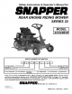
Safety Instructions & Operator's Manual for REAR ENGINE RIDING MOWER SERIES 22 MODEL 421622BVE MODEL NUMBER EXPLANATION CUTTING WIDTH ENGINE HP SERIES DESIGNATION 42 - 42" Cutting Deck I 16-16.
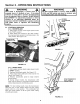
IMPORTANT SAFETY INSTRUCTIONS WARNING: This powerful cutting machine is capable of amputating hands and feet and can throw objects that can cause injury and damage! Failure to comply with the following SAFETY instructions could result in serious injury or death to the operator or other persons. The owner of the machine must understand these instructions and must allow only persons who understand these instructions to operate machine.
IMPORTANT SAFETY INSTRUCTIONS PREPARATION (Continued From Previous Page) 7. Keep people and pets out of mowing area. Immediately STOP blades, STOP engine, and STOP machine if anyone enters the area. 8. Check shields, deflectors, switches, blade controls and other safety devices frequently for proper operation and location. 9. Make sure all safety decals are clearly legible. Replace if damaged. 10. Protect yourself when mowing and wear safety glasses, long pants and substantial footwear. 11.
TABLE l OF CONTENTS IMPORTANT SAFETY INSTRUCTIONS ......................................................................... 2-3 TABLE OF CONTENTS ...................................................................................................... 4 SECTION 1 - FAMILIARIZATION ....................................................................................... 5 SECTION 2 - OPERATING INSTRUCTIONS ................................................................ 6-12 Pre-start Checklist ...............
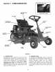
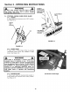
Section 1 - FAMILIARIZATION ENGINE SPEED AND CHOKE FUEL FILLER CAP AND VENT LOCATED LEFT OF SEAT FUEL TANK DECK LIFT TRANSMISSION SHIFT LEVER CLUTCH/BRAKE PEDAL PARK BRAKE LATCH OVERRIDE LEVER DISCHARGE DEFLECTOR BLADE LEVER BLADE PEDALS '_ FIGURE 1.1 1.1 INTRODUCTION This manual has been prepared for the operator's of the SNAPPER Rear Engine Rider.
Section 2 - OPERATING 2.1 INSTRUCTIONS PRE-START CHECK LIST Make the following checks and perform the service required before each start-up. 2.1.1. Check tires and add or release air as needed to bring pressure to 12 psi in front and 12 psi in rear tires. 2.1.2. Check guards, deflectors and covers to make sure all are in place and securely tightened. 2.1.3. Check engine oil and add oil as needed to bring level up to the FULL mark. Refer to engine owner's manual for oil specifications. See Figure 2.1.
Section 2 - OPERATING 2.3 INSTRUCTIONS TO START ENGINE, PUSH CLUTCH/BRAKE PEDAL ALL THE WAY DOWN STARTING & OPERATION 2.3.1. ENGINE (ELECTRIC START) IMPORTANT: When the ignition key is turned to "START", the engine will turn over, but will not start unless the Clutch/Brake pedal is pressed all the way down, the Blade Lever is in the "Off" position (See Figure 2.4). The operator should be in the seat. Start engine as follows: 1. Move transmission shift lever to (N) Neutral position.
Section 2 - OPERATING 2.3 INSTRUCTIONS STARTING & OPERATION 2.3.1. ENGINE (ELECTRIC START) (Continued) 8. Should the battery be too weak to start the engine, Refer to Section "ENGINE (MANUAL START)" to manually start the electric start engines. 2.3.2. ENGINE (MANUAL START) IMPORTANT: When the ignition key is turned to "RUN", and the recoil handle is pulled, the engine will turn over, but will not start unless the Clutch/Brake Pedal is pressed all the way down with Parking Brake engaged (See Figure 2.
Section 2 - OPERATING INSTRUCTIONS WARNING Once blade is disengaged, it should come to a complete stop in 3 seconds or less. If the blade continues to rotate after 3 seconds, the blade brake must be adjusted. Refer to Section "BLADE BRAKE ADJUSTMENT" for adjustment procedures or return machine to an authorized SNAPPER dealer for adjustment. DO NOT CONTINUE to operate machine until blade brake is adjusted and functioning properly. 2.3 ik WARNING I DO NOT operate blades in reverse. STOP BLADES.
Section 2 - OPERATING WARNING INSTRUCTIONS A TO APPLY BRAKES, PUSH CLUTCH/BRAKE PEDAL ALL THE WAY DOWN, DO NOT leave machine with the engine running. Stop engine. Stop blade. Shift to neutral. Engage parking brake. Remove key. 2.4 STOPPING - ENGINE, WHEEL DRIVE, BLADE 2.4.1. ENGINE 1. Stop engine by turning key to the "OFF" position. See Figure 2.13. TURN TO "OFF" POSITION PARK BJ_ EY _IP LATCH SHOWN ENGAGED FIGURE 2.14 FIGURE 2.13 2.4.2. WHEEL DRIVE 1.
Section 2 - OPERATING 2.4 INSTRUCTIONS 2.5. CUTTING HEIGHT ADJUSTMENT 1. Adjust cutting height as desired to any one of six positions using deck lift lever. When in desired height of cut, release latch, then try to move deck lift lever to ensure lift lever latch is fully engaged. See Figure 2.18. STOPPING - ENGINE, WHEEL DRIVE, BLADE 2.4.4. PARK BRAKE 1. Engage park brake by pushing clutch/brake "DOWN" and moving the park brake latch over "ENGAGED" position.
Section 2 - OPERATING 2.6 INSTRUCTIONS REVERSE LOCKOUT MECHANISM 2.6.1. Reverse Lockout Mechanism Override 1. Stop machine. Stop blade. 2. Depress and hold Override Lever. 3. Depress and hold Blade Pedals. Release Override Lever. 4. Move blade lever forward to "ON" position. Data indicates that tragic back-over accidents occur each year. These accidents usually involve unsupervised children.
Section 3 - MAINTENANCE 5. After all the oil has drained, close the drain and wipe up any oil that may have spilled. See Figure 3.1. Dispose of oil properly. 6. Fill engine crankcase with new oil. Refer to your engine owner's manual for oil specifications. 7. Change oil filter at every oil change. Refer to your engine owner's manual for service instructions. WARNING DO NOT attempt any adjustments, maintenance, service or repairs with the engine running. STOP engine. STOP blade. Engage parking brake.
Section 3 - MAINTENANCE TOP VIEW OF BELT ROUTING WARNING DO NOT attempt any adjustments, maintenance, service or repairs with the engine running. STOP engine. STOP blade. Engage parking brake. Remove key. Remove spark plug wire from spark plug and secure away from plug. Engine and components are HOT. Avoid serious burns, allow all parts to cool before working on machine. Fuel Filler Cap and vent must be closed securely to prevent fuel spillage. 3.2 LEFT SPINDLE PULLEY SERVICE - AFTER FIRST 5 HOURS 3.2.4.
Section 3- MAINTENANCE 3.2.8. REVERSE LOCKOUT MECHANISM Check function of Reverse Lockout Mechanism engine off. 1. Depress and hold blade pedals. 2. Depress and hold clutch/brake pedal. 3. Shift lever must not go into reverse. 3. Carefully stand Rear Engine Rider on rear bumper. 4. Clean underside of mower deck, removing all accumulation of grass clippings and debris. 5. Clean top of deck, removing all grass clippings and debris. with 3.3.5. MOWER BLADE SPINDLE- LUBRICATION 1.
Section 3 - MAINTENANCE WARNING DO NOT attempt any adjustments, maintenance, service or repairs with the engine running. STOP engine. STOP blade. Engage parking brake. Remove key. Remove spark plug wire from spark plug and secure away from plug. Engine and components are HOT. Avoid serious bums, allow all parts to cool before working on machine. Fuel Filler Cap and vent must be closed securely to prevent fuel spillage. 3.3 SERVICE - EVERY 25 OPERATING HOURS (Continued from previous page) 3.3.9.
Section 3 - MAINTENANCE 3.7 WARNING DO NOT attempt any adjustments, maintenance, service or repairs with the engine running. STOP engine. STOP blade. Engage parking brake. Remove key. Remove spark plug wire from spark plug and secure away from plug. Engine and components are HOT. Avoid serious burns, allow all parts to cool before working on machine. Fuel Filler Cap and vent must be closed securely to prevent fuel spillage. 3.5 3.
Section 4 - ADJUSTMENTS & REPAIR 4.2.2. BLADE BRAKE ADJUSTMENT The automatic Blade Brake should stop the blades within 3 seconds anytime the blades are disengaged by moving blade lever to the "OFF" position or by releasing the Blade Pedals. When the Blade Brake is properly adjusted there should be 1/16" to 1/8" clearance between the Blade Engagement Lever and the back of the Latch Plate. Check this by disengaging the Blade Lever and depressing the Blade Pedals as shown in Figure 4.2.
Section 4 - ADJUSTMENTS & REPAIR 4.2.4. MOWER DECK ADJUSTMENT (Side To Side Levelness) Before making deck leveling adjustments, check the tire pressure. Front tires 12 psi, rear tires 12 psi. If tires are properly inflated and mowing is still uneven, adjust side-to-side deck levelness as follows: 1. Place Rider on a smooth level surface. 2. Turn engine off and remove key, remove spark plug wire from spark plug and secure wire away from plug. 3.
Section 4 - ADJUSTMENTS & REPAIR 4.2 MOWER DECK & COMPONENT ADJUSTMENTS 4.2.6. CUTTING HEIGHT ADJUSTMENT The cutting height range of the mower can be adjusted. 1. Place the Rear Engine Rider on a smooth, level surface. 2. Place blocks under mower deck. Lower deck with deck lift lever until weight of mower is supported on the blocks. 3. Loosen lift quadrant mounting bolts. Raise or lower lift quadrant as desired. See Figure 4.6.
Section 4 - ADJUSTMENTS & REPAIR 4.3.2. SERVICE BRAKE/PARK BRAKE ADJUSTMENT Test the wheel brake on a dry concrete surface. When properly adjusted, the Rear Engine Rider will stop within 5 feet from fastest speed. If stopping distance is more than 5 feet, the wheel brake should be adjusted as follows: 1. Follow WARNING statement found on this page. 2. Check fuel level in tank. If over 3/4 full, remove tank. Refer to Section "REMOVING FUEL TANK". If 3/4 or less, proceed to next step. 3.
Section 4 - ADJUSTMENTS & REPAIR WARNING BRAKE CABLE CASE DO NOT attempt any adjustments, maintenance, service or repairs with the engine running. STOP engine. STOP blade. Engage parking brake. Remove key. Remove spark plug wire from spark plug and secure away from plug. Engine and components are HOT. Avoid serious burns, allow all parts to cool before working on machine. Fuel Filler Cap and vent must be closed securely to prevent fuel spillage. 4.3 REAR ENGINE RIDER DRIVE COMPONENTS 4.3.2.
Section 4 - ADJUSTMENTS & REPAIR WARNING DO NOT attempt any adjustments, maintenance, service or repairs with the engine running. STOP engine. STOP blade. Engage parking brake. Remove key. Remove spark plug wire from spark plug and secure away from plug. Engine and components are HOT. Avoid serious burns, allow all parts to cool before working on machine. Fuel Filler Cap and vent must be closed securely to prevent fuel spillage.
Section 4 - ADJUSTMENTS & REPAIR WARNING REMOVE STATIONARY IDLER DO NOT attempt any adjustments, maintenance, service or repairs with the engine running. STOP engine. STOP blade. Engage parking brake. Remove key. Remove spark plug wire from spark plug and secure away from plug. Engine and components are HOT. Avoid serious burns, allow all parts to cool before working on machine. Fuel Filler Cap and vent must be closed securely to prevent fuel spillage. REMOVE IDLER 4.5.2. BELT REPLACEMENT 1.
Section 4 - ADJUSTMENTS & REPAIR RED POSITIVE WARNING DO NOT attempt any adjustments, maintenance, service or repairs with the engine running. Stop engine. Stop blade. Engage parking brake. Remove key. Remove spark plug wire from spark plug and secure away from plug. Engine and components are HOT. Avoid serious burns, allow all parts to cool before working on machine. Fuel Filler Cap and Vent must be closed securely to prevent fuel spillage.
Section 4 - ADJUSTMENTS & REPAIR WARNING The electrolyte (acid) produces a highly explosive gas. Keep all sparks, flame and fire away from area when charging battery or when handling electrolyte or battery. Electrolyte (acid) is a highly corrosive liquid. Wear eye protection. Wash affected areas immediately after having eye or skin contact with electrolyte (acid). Battery acid is corrosive. Rinse empty acid containers with water and mutilate before discarding.
Section 4 - ADJUSTMENTS 4.6.6. & REPAIR BATTERY TESTING Batten/Condition State of Charge 100% Charged w/Sulfate 100% Charged 75% Charged 50% Charged 25% Charged 0% Charged Syringe Hydrometer 1.280 1.265 1.210 1.160 1.120 Less than 1.100 Stop SNAPPER PART NO. Chart Digital Voltmeter 12.80v 12.60v 12.40v 12.10v 11.90v Less than 11.
TROUBLESHOOTING PROBLEM EngineWill Not Start Using Recoil Starter Engine Will Not Start Using Electric Starter PROBABLE CAUSE CORRECTIVE ACTION , Fuel tank empty. 2. Engine needs choking. 3. Spark plug wire disconnected. 4. Faulty parking brake, blade or ignition switch. 5. Park brake not engaged. 6. Ignition is in the OFF position. 1. Fuel tank empty. 2. Engine needs choking. 3. Spark plug wire disconnected. 4. Faulty parking brake, blade or ignition switch. 5. Park brake not engaged. 6. Blown Fuse. 7.
TROUBLESHOOTING PROBLEM Rider Will Not Move Loss Of Traction Blade(s) Not Cutting Cutting Grass Improperly PROBABLE CAUSE CORRECTIVE ACTION 1. Drive disc worn or dama,qed. 2. Rubber drive disc is not tracking properly on drive disc. 3. Tapered axle bolt and nut missing. 4. Axle bearing seized. 5. Insufficient lubrication in chain case or transmission/differential. Discharge 1. Move lever to the "ON" position. 2. Adjust or replace mower belt. 3. Sharpen or replace cutting blade. 1.
MAINTENANCE SUBJECT SCHEDULE 6 HOURS 25 HOURS 60 HOURS 100 HOURS Engine Page 6 X Tires Check Pressures Page 6 X Engine Initial Oil Change Page 13 Engine Periodic Oil Change Page 15 Air Pre-Cleaner Service Sponge PreCleaner Element Engine Manual Air Cleaner Replace Element Engine Manual Spark Plug Replace Plugs Engine Manual X Fuel Filter Replace Filter Page 16 X Engine Cooling System Battery Clean Shrouds & Fins Engine Manual Check Electrolyte Page 26 Battery Charge Bat
3 YEAR LIMITED WARRANTY For three (3) years from purchase date for the original purchaser's residential, non-commercial use, SNAPPER, through any authorized SNAPPER dealer will replace, free of charge (except for taxes where applicable), any part or parts found upon examination by the factory at McDonough, Georgia, to be defective in material or workmanship or both.
PRIMARY MAINTENANCE an illustration of how dirt can ge your engine & how reasonable maintenance can protect it! Snapper uses the best available engines and components in their products in order to provide long, satisfactory service. However, proper care is essential In prolonging engine life.
PRIMARY MAINTENANCE g that dirt will quickly ruin an engine, manufacturers equip their engines with extremely efficient air cleaners to out the harmful dirt. The engine must gulp about 12,000 gallons of air for every gallon of used. Because of Its working environment, the air available to your Snapper engine Is " heavily saturated with airborne dirt particles. As the dirt particles are stopped, they build up and begin to clog the outside of the filter.
PRIMARY MAINTENANCE Air is also needed to keep your engine cool. Dirt, dust & debris build up to restrict and clog cooling air Intake screens and fins. Clean screens and fins at frequent Intervals. The engine blower housing and shrouds should be removed at least once each season or more often under dry, dusty conditions for a thorough cleaning of fins. Generally, wash foam-type filters In a dishwashlng detergent and water solution. Rinse and wring dry, then saturate with oil and squeeze out excess.
PRIMARY MAINTENANCE On 2-cycle engines, lubricaUon must be provided by an exact mixture of gasoline and 2-cycle air-cooled engine oil. A 2-cycle engine that Is mistakenly run on straight gasoline will be ruined in less than 5 mlnutesl If you keep straight gasoline In addition to pre-mixed 2-cycle engine fuel, be sure the containers are clearly marked to avoid mix-up. Snapper 2-cycle engines require a 32 to 1 mixture of gasoline and BIA certified TC-W oil such as Snapper's 2-cycle engine o11.
Safety Instructions & Operator's Manual for REAR ENGINE RIDING MOWER SERIES 22 IMPORTANT Snapper products are built using engines that meet or exceed all applicable emissions requirements on the date manufactured. The labels on those engines contain very important emissions information and critical safety warnings. Read, Understand, and Follow all warnings and instructions in this manual, the engine manual, and on the machine, engine and attachments.
Safety Instructions & Operator's Manual for REAR ENGINE RIDING MOWER SERIES 22 MODEL 421622BVE MODEL NUMBER EXPLANATION CUTTING WIDTH ENGINE HP SERIES DESIGNATION 42 - 42" Cutting Deck I 16-16.
IMPORTANT SAFETY INSTRUCTIONS WARNING: This powerful cutting machine is capable of amputating hands and feet and can throw objects that can cause injury and damage! Failure to comply with the following SAFETY instructions could result in serious injury or death to the operator or other persons. The owner of the machine must understand these instructions and must allow only persons who understand these instructions to operate machine.
IMPORTANT SAFETY INSTRUCTIONS PREPARATION (Continued From Previous Page) 7. Keep people and pets out of mowing area. Immediately STOP blades, STOP engine, and STOP machine if anyone enters the area. 8. Check shields, deflectors, switches, blade controls and other safety devices frequently for proper operation and location. 9. Make sure all safety decals are clearly legible. Replace if damaged. 10. Protect yourself when mowing and wear safety glasses, long pants and substantial footwear. 11.
TABLE l OF CONTENTS IMPORTANT SAFETY INSTRUCTIONS ......................................................................... 2-3 TABLE OF CONTENTS ...................................................................................................... 4 SECTION 1 - FAMILIARIZATION ....................................................................................... 5 SECTION 2 - OPERATING INSTRUCTIONS ................................................................ 6-12 Pre-start Checklist ...............
Section 1 - FAMILIARIZATION ENGINE SPEED AND CHOKE FUEL FILLER CAP AND VENT LOCATED LEFT OF SEAT FUEL TANK DECK LIFT TRANSMISSION SHIFT LEVER CLUTCH/BRAKE PEDAL PARK BRAKE LATCH OVERRIDE LEVER DISCHARGE DEFLECTOR BLADE LEVER BLADE PEDALS '_ FIGURE 1.1 1.1 INTRODUCTION This manual has been prepared for the operator's of the SNAPPER Rear Engine Rider.
Section 2 - OPERATING 2.1 INSTRUCTIONS PRE-START CHECK LIST Make the following checks and perform the service required before each start-up. 2.1.1. Check tires and add or release air as needed to bring pressure to 12 psi in front and 12 psi in rear tires. 2.1.2. Check guards, deflectors and covers to make sure all are in place and securely tightened. 2.1.3. Check engine oil and add oil as needed to bring level up to the FULL mark. Refer to engine owner's manual for oil specifications. See Figure 2.1.
Section 2 - OPERATING 2.3 INSTRUCTIONS TO START ENGINE, PUSH CLUTCH/BRAKE PEDAL ALL THE WAY DOWN STARTING & OPERATION 2.3.1. ENGINE (ELECTRIC START) IMPORTANT: When the ignition key is turned to "START", the engine will turn over, but will not start unless the Clutch/Brake pedal is pressed all the way down, the Blade Lever is in the "Off" position (See Figure 2.4). The operator should be in the seat. Start engine as follows: 1. Move transmission shift lever to (N) Neutral position.
Section 2 - OPERATING 2.3 INSTRUCTIONS STARTING & OPERATION 2.3.1. ENGINE (ELECTRIC START) (Continued) 8. Should the battery be too weak to start the engine, Refer to Section "ENGINE (MANUAL START)" to manually start the electric start engines. 2.3.2. ENGINE (MANUAL START) IMPORTANT: When the ignition key is turned to "RUN", and the recoil handle is pulled, the engine will turn over, but will not start unless the Clutch/Brake Pedal is pressed all the way down with Parking Brake engaged (See Figure 2.
Section 2 - OPERATING INSTRUCTIONS WARNING Once blade is disengaged, it should come to a complete stop in 3 seconds or less. If the blade continues to rotate after 3 seconds, the blade brake must be adjusted. Refer to Section "BLADE BRAKE ADJUSTMENT" for adjustment procedures or return machine to an authorized SNAPPER dealer for adjustment. DO NOT CONTINUE to operate machine until blade brake is adjusted and functioning properly. 2.3 ik WARNING I DO NOT operate blades in reverse. STOP BLADES.
Section 2 - OPERATING WARNING INSTRUCTIONS A TO APPLY BRAKES, PUSH CLUTCH/BRAKE PEDAL ALL THE WAY DOWN, DO NOT leave machine with the engine running. Stop engine. Stop blade. Shift to neutral. Engage parking brake. Remove key. 2.4 STOPPING - ENGINE, WHEEL DRIVE, BLADE 2.4.1. ENGINE 1. Stop engine by turning key to the "OFF" position. See Figure 2.13. TURN TO "OFF" POSITION PARK BJ_ EY _IP LATCH SHOWN ENGAGED FIGURE 2.14 FIGURE 2.13 2.4.2. WHEEL DRIVE 1.
Section 2 - OPERATING 2.4 INSTRUCTIONS 2.5. CUTTING HEIGHT ADJUSTMENT 1. Adjust cutting height as desired to any one of six positions using deck lift lever. When in desired height of cut, release latch, then try to move deck lift lever to ensure lift lever latch is fully engaged. See Figure 2.18. STOPPING - ENGINE, WHEEL DRIVE, BLADE 2.4.4. PARK BRAKE 1. Engage park brake by pushing clutch/brake "DOWN" and moving the park brake latch over "ENGAGED" position.
Section 2 - OPERATING 2.6 INSTRUCTIONS REVERSE LOCKOUT MECHANISM 2.6.1. Reverse Lockout Mechanism Override 1. Stop machine. Stop blade. 2. Depress and hold Override Lever. 3. Depress and hold Blade Pedals. Release Override Lever. 4. Move blade lever forward to "ON" position. Data indicates that tragic back-over accidents occur each year. These accidents usually involve unsupervised children.
Section 3 - MAINTENANCE 5. After all the oil has drained, close the drain and wipe up any oil that may have spilled. See Figure 3.1. Dispose of oil properly. 6. Fill engine crankcase with new oil. Refer to your engine owner's manual for oil specifications. 7. Change oil filter at every oil change. Refer to your engine owner's manual for service instructions. WARNING DO NOT attempt any adjustments, maintenance, service or repairs with the engine running. STOP engine. STOP blade. Engage parking brake.
Section 3 - MAINTENANCE TOP VIEW OF BELT ROUTING WARNING DO NOT attempt any adjustments, maintenance, service or repairs with the engine running. STOP engine. STOP blade. Engage parking brake. Remove key. Remove spark plug wire from spark plug and secure away from plug. Engine and components are HOT. Avoid serious burns, allow all parts to cool before working on machine. Fuel Filler Cap and vent must be closed securely to prevent fuel spillage. 3.2 LEFT SPINDLE PULLEY SERVICE - AFTER FIRST 5 HOURS 3.2.4.
Section 3- MAINTENANCE 3.2.8. REVERSE LOCKOUT MECHANISM Check function of Reverse Lockout Mechanism engine off. 1. Depress and hold blade pedals. 2. Depress and hold clutch/brake pedal. 3. Shift lever must not go into reverse. 3. Carefully stand Rear Engine Rider on rear bumper. 4. Clean underside of mower deck, removing all accumulation of grass clippings and debris. 5. Clean top of deck, removing all grass clippings and debris. with 3.3.5. MOWER BLADE SPINDLE- LUBRICATION 1.
Section 3 - MAINTENANCE WARNING DO NOT attempt any adjustments, maintenance, service or repairs with the engine running. STOP engine. STOP blade. Engage parking brake. Remove key. Remove spark plug wire from spark plug and secure away from plug. Engine and components are HOT. Avoid serious bums, allow all parts to cool before working on machine. Fuel Filler Cap and vent must be closed securely to prevent fuel spillage. 3.3 SERVICE - EVERY 25 OPERATING HOURS (Continued from previous page) 3.3.9.
Section 3 - MAINTENANCE 3.7 WARNING DO NOT attempt any adjustments, maintenance, service or repairs with the engine running. STOP engine. STOP blade. Engage parking brake. Remove key. Remove spark plug wire from spark plug and secure away from plug. Engine and components are HOT. Avoid serious burns, allow all parts to cool before working on machine. Fuel Filler Cap and vent must be closed securely to prevent fuel spillage. 3.5 3.
Section 4 - ADJUSTMENTS & REPAIR 4.2.2. BLADE BRAKE ADJUSTMENT The automatic Blade Brake should stop the blades within 3 seconds anytime the blades are disengaged by moving blade lever to the "OFF" position or by releasing the Blade Pedals. When the Blade Brake is properly adjusted there should be 1/16" to 1/8" clearance between the Blade Engagement Lever and the back of the Latch Plate. Check this by disengaging the Blade Lever and depressing the Blade Pedals as shown in Figure 4.2.
Section 4 - ADJUSTMENTS & REPAIR 4.2.4. MOWER DECK ADJUSTMENT (Side To Side Levelness) Before making deck leveling adjustments, check the tire pressure. Front tires 12 psi, rear tires 12 psi. If tires are properly inflated and mowing is still uneven, adjust side-to-side deck levelness as follows: 1. Place Rider on a smooth level surface. 2. Turn engine off and remove key, remove spark plug wire from spark plug and secure wire away from plug. 3.
Section 4 - ADJUSTMENTS & REPAIR 4.2 MOWER DECK & COMPONENT ADJUSTMENTS 4.2.6. CUTTING HEIGHT ADJUSTMENT The cutting height range of the mower can be adjusted. 1. Place the Rear Engine Rider on a smooth, level surface. 2. Place blocks under mower deck. Lower deck with deck lift lever until weight of mower is supported on the blocks. 3. Loosen lift quadrant mounting bolts. Raise or lower lift quadrant as desired. See Figure 4.6.
Section 4 - ADJUSTMENTS & REPAIR 4.3.2. SERVICE BRAKE/PARK BRAKE ADJUSTMENT Test the wheel brake on a dry concrete surface. When properly adjusted, the Rear Engine Rider will stop within 5 feet from fastest speed. If stopping distance is more than 5 feet, the wheel brake should be adjusted as follows: 1. Follow WARNING statement found on this page. 2. Check fuel level in tank. If over 3/4 full, remove tank. Refer to Section "REMOVING FUEL TANK". If 3/4 or less, proceed to next step. 3.
Section 4 - ADJUSTMENTS & REPAIR WARNING BRAKE CABLE CASE DO NOT attempt any adjustments, maintenance, service or repairs with the engine running. STOP engine. STOP blade. Engage parking brake. Remove key. Remove spark plug wire from spark plug and secure away from plug. Engine and components are HOT. Avoid serious burns, allow all parts to cool before working on machine. Fuel Filler Cap and vent must be closed securely to prevent fuel spillage. 4.3 REAR ENGINE RIDER DRIVE COMPONENTS 4.3.2.
Section 4 - ADJUSTMENTS & REPAIR WARNING DO NOT attempt any adjustments, maintenance, service or repairs with the engine running. STOP engine. STOP blade. Engage parking brake. Remove key. Remove spark plug wire from spark plug and secure away from plug. Engine and components are HOT. Avoid serious burns, allow all parts to cool before working on machine. Fuel Filler Cap and vent must be closed securely to prevent fuel spillage.
Section 4 - ADJUSTMENTS & REPAIR WARNING REMOVE STATIONARY IDLER DO NOT attempt any adjustments, maintenance, service or repairs with the engine running. STOP engine. STOP blade. Engage parking brake. Remove key. Remove spark plug wire from spark plug and secure away from plug. Engine and components are HOT. Avoid serious burns, allow all parts to cool before working on machine. Fuel Filler Cap and vent must be closed securely to prevent fuel spillage. REMOVE IDLER 4.5.2. BELT REPLACEMENT 1.
Section 4 - ADJUSTMENTS & REPAIR RED POSITIVE WARNING DO NOT attempt any adjustments, maintenance, service or repairs with the engine running. Stop engine. Stop blade. Engage parking brake. Remove key. Remove spark plug wire from spark plug and secure away from plug. Engine and components are HOT. Avoid serious burns, allow all parts to cool before working on machine. Fuel Filler Cap and Vent must be closed securely to prevent fuel spillage.
Section 4 - ADJUSTMENTS & REPAIR WARNING The electrolyte (acid) produces a highly explosive gas. Keep all sparks, flame and fire away from area when charging battery or when handling electrolyte or battery. Electrolyte (acid) is a highly corrosive liquid. Wear eye protection. Wash affected areas immediately after having eye or skin contact with electrolyte (acid). Battery acid is corrosive. Rinse empty acid containers with water and mutilate before discarding.
Section 4 - ADJUSTMENTS 4.6.6. & REPAIR BATTERY TESTING Batten/Condition State of Charge 100% Charged w/Sulfate 100% Charged 75% Charged 50% Charged 25% Charged 0% Charged Syringe Hydrometer 1.280 1.265 1.210 1.160 1.120 Less than 1.100 Stop SNAPPER PART NO. Chart Digital Voltmeter 12.80v 12.60v 12.40v 12.10v 11.90v Less than 11.
TROUBLESHOOTING PROBLEM EngineWill Not Start Using Recoil Starter Engine Will Not Start Using Electric Starter PROBABLE CAUSE CORRECTIVE ACTION , Fuel tank empty. 2. Engine needs choking. 3. Spark plug wire disconnected. 4. Faulty parking brake, blade or ignition switch. 5. Park brake not engaged. 6. Ignition is in the OFF position. 1. Fuel tank empty. 2. Engine needs choking. 3. Spark plug wire disconnected. 4. Faulty parking brake, blade or ignition switch. 5. Park brake not engaged. 6. Blown Fuse. 7.
TROUBLESHOOTING PROBLEM Rider Will Not Move Loss Of Traction Blade(s) Not Cutting Cutting Grass Improperly PROBABLE CAUSE CORRECTIVE ACTION 1. Drive disc worn or dama,qed. 2. Rubber drive disc is not tracking properly on drive disc. 3. Tapered axle bolt and nut missing. 4. Axle bearing seized. 5. Insufficient lubrication in chain case or transmission/differential. Discharge 1. Move lever to the "ON" position. 2. Adjust or replace mower belt. 3. Sharpen or replace cutting blade. 1.
MAINTENANCE SUBJECT SCHEDULE 6 HOURS 25 HOURS 60 HOURS 100 HOURS Engine Page 6 X Tires Check Pressures Page 6 X Engine Initial Oil Change Page 13 Engine Periodic Oil Change Page 15 Air Pre-Cleaner Service Sponge PreCleaner Element Engine Manual Air Cleaner Replace Element Engine Manual Spark Plug Replace Plugs Engine Manual X Fuel Filter Replace Filter Page 16 X Engine Cooling System Battery Clean Shrouds & Fins Engine Manual Check Electrolyte Page 26 Battery Charge Bat
3 YEAR LIMITED WARRANTY For three (3) years from purchase date for the original purchaser's residential, non-commercial use, SNAPPER, through any authorized SNAPPER dealer will replace, free of charge (except for taxes where applicable), any part or parts found upon examination by the factory at McDonough, Georgia, to be defective in material or workmanship or both.
PRIMARY MAINTENANCE an illustration of how dirt can ge your engine & how reasonable maintenance can protect it! Snapper uses the best available engines and components in their products in order to provide long, satisfactory service. However, proper care is essential In prolonging engine life.
PRIMARY MAINTENANCE g that dirt will quickly ruin an engine, manufacturers equip their engines with extremely efficient air cleaners to out the harmful dirt. The engine must gulp about 12,000 gallons of air for every gallon of used. Because of Its working environment, the air available to your Snapper engine Is " heavily saturated with airborne dirt particles. As the dirt particles are stopped, they build up and begin to clog the outside of the filter.
PRIMARY MAINTENANCE Air is also needed to keep your engine cool. Dirt, dust & debris build up to restrict and clog cooling air Intake screens and fins. Clean screens and fins at frequent Intervals. The engine blower housing and shrouds should be removed at least once each season or more often under dry, dusty conditions for a thorough cleaning of fins. Generally, wash foam-type filters In a dishwashlng detergent and water solution. Rinse and wring dry, then saturate with oil and squeeze out excess.
PRIMARY MAINTENANCE On 2-cycle engines, lubricaUon must be provided by an exact mixture of gasoline and 2-cycle air-cooled engine oil. A 2-cycle engine that Is mistakenly run on straight gasoline will be ruined in less than 5 mlnutesl If you keep straight gasoline In addition to pre-mixed 2-cycle engine fuel, be sure the containers are clearly marked to avoid mix-up. Snapper 2-cycle engines require a 32 to 1 mixture of gasoline and BIA certified TC-W oil such as Snapper's 2-cycle engine o11.
Safety Instructions & Operator's Manual for REAR ENGINE RIDING MOWER SERIES 22 IMPORTANT Snapper products are built using engines that meet or exceed all applicable emissions requirements on the date manufactured. The labels on those engines contain very important emissions information and critical safety warnings. Read, Understand, and Follow all warnings and instructions in this manual, the engine manual, and on the machine, engine and attachments.