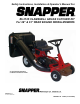
Safety Instructions, Installation & Operator’s Manual For #6-3125 CLAMSHELL GRASS CATCHER KIT For 28” & 33” REAR ENGINE RIDING MOWERS 28” REAR ENGINE RIDER WITH CLAMSHELL BAGGER KIT SHOWN COPYRIGHT © 2000 SNAPPER INC. ALL RIGHTS RESERVED MANUAL No. 7-2887 (I.R.
IMPORTANT SAFETY INSTRUCTIONS WARNING All safety instructions and operating instructions in the manuals provided with the Snapper Rear Engine Rider and this Grass Catcher attachment must be followed. Read, understand, and follow ALL instructions and warnings in the Operator’s Manual provided with the machine, with this attachment, and ALL instructions and warnings on the machine, engine and attachment.
TABLE OF CONTENTS IMPORTANT SAFETY INSTRUCTIONS ..............................................................2 TABLE OF CONTENTS........................................................................................3 SECTION 1 - ASSEMBLY INSTRUCTIONS..................................................... 3-9 Introduction.............................................................................................................................. 3 Right & Left Bumper Bracket Installation ....................
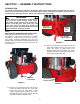
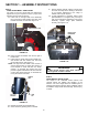
SECTION 1 – ASSEMBLY INSTRUCTIONS INTRODUCTION The 6-3125 Clamshell Grass Catcher kit fits Snapper Rear Engine Riding mowers equipped with 28” and 33” decks. Use the following instructions to assemble the grass catcher components and prepare your machine for collecting grass clippings and leaves. Follow and complete each step carefully. WARNING DO NOT attempt any adjustments, maintenance or service with the engine running. STOP engine. STOP blade. Engage parking brake. Remove key.
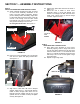
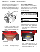
SECTION 1 – ASSEMBLY INSTRUCTIONS D. Tighten hitch plate bolts that were left loose in STEP 2, “A”. E. Attach left end of baffle to Front Cover Assembly. Place (1) 3/16” Flat Washer over #10-24 x 3/4” Flange Lock Bolt and insert from inside cover. Secure with (1) #10-24 Flange Lock Nut. Tighten securely. STEP 2 HITCH PLATE AND HEAT SHIELD INSTALLATION A. Attach triangular shaped Hitch Plate to bottom of Front Cover Assembly.
SECTION 1 – ASSEMBLY INSTRUCTIONS F. Actuate Catcher Handle. Catcher should open and close smoothly with no binding. If the action is not smooth, adjustment to the Hinge or Handle Links may be required. G. If hinge adjustment is required, loosen hinge plate hardware. For a tighter seal, push top of rear cover frame firmly against the Front Cover Assembly. Tighten hinge plate hardware securely. See Figure 1.10.
SECTION 1 – ASSEMBLY INSTRUCTIONS STEP 6 AIR LIFT KIT, #6-0480 INSTALLATION Some Rider models will not require the installation of the Air Lift Kit included with the Grass Catcher. Inspect the blade on your mower. If the blade does not have mounting holes for the Air Lift Kit, the blade is a High Lift version and does not require the kit. If the blade does have the holes in the lift area of the blade, install the Lift Kit. Installation instructions and the necessary hardware are included with the Air Lifts.
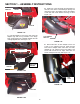
SECTION 1 – ASSEMBLY INSTRUCTIONS HINGE NUT D. Install one of the previously removed bolts into the hole in the center of the discharge opening and through the hole in the adapter. Secure the adapter to the deck with a flat washer and wing nut. See Figure 1.16. SPRING HINGE PIN FIGURE 1.14 C. Hold the adapter in front of the deck. Align the adapter lugs with the lug retainers in the hinge. Push or lightly tap front of adapter towards the rear until tight against deck. See Figure 1.15.
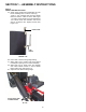
SECTION 1 – ASSEMBLY INSTRUCTIONS STEP 8 GRASS TUBE INSTALLATION A. Attach Tube Handle and Handle Base to Tube before installing Tube to catcher. Insert (2) 1/4-20 x 3/4” Carriage bolts through Handle Base and holes in Tube as shown. See Figure 1.18. Place Tube Handle over bolts followed by 1/4” Internal Tooth lock washers and secure with (2) 1/4-20 hex nuts. Tighten securely. See Figure 1.18. HANDLE BASE TUBE HANDLE FIGURE 1.18 B. Place deck in lowest cutting height setting. C.
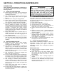
SECTION 2– OPERATION & MAINTENANCE INTRODUCTION Follow operation and maintenance instructions in the Operator’s Manual provided with the Snapper Rear Engine Rider. WARNING DO NOT attempt to remove any clogs from deck, adapter, or tube with engine or blade running. STOP engine. STOP blade. Engage parking brake. Remove key. Make sure blade and all rotating components have come to a complete stop before removing or unclogging any catcher component. 2.1 GRASS CATCHER OPERATION A.
CLAMSHELL ASSEMBLY COMPONENTS 12 30 18 15 5 19 12 41 14 17 33 10 43 5 12 30 11 40 4 6 48 29 7 9 30 13 49 31 3 42 47 38 23 51 52 28 1 32 39 36 55 53 25 54 21 35 34 50 44 22 24 26 34 37 27 11
CLAMSHELL ASSEMBLY COMPONENTS ITEM PART NO.
Safety Instructions, Installation & Operator’s Manual For #6-3125 CLAMSHELL GRASS CATCHER KIT For 28” & 33” REAR ENGINE RIDING MOWERS COPYRIGHT © 2000 SNAPPER INC. ALL RIGHTS RESERVED MANUAL No. 7-2887 (I.R.