Safety Instructions & Operator's Manual for ZERO-TURN RIDING MOWER 500Z Series 26HP Zero-Turn Riders 00 Mfg. No. Description 5900731 500ZB2648 Snapper 26HP 500Z Zero-Turn Rider with 48” Mower 5101453 Revision IR Rev.
Thank you for purchasing this quality-built Snapper product. We’re pleased that you’ve placed your confidence in the Snapper brand. When operated and maintained according to the instructions in this manual, your Snapper product will provide many years of dependable service. This manual contains safety information to make you aware of the hazards and risks associated with this machine and how to avoid them.
Table of Contents Safety Controls Operator Safety .....................................................2 Safety Rules and Information ...........................................2 Safety Decals ....................................................................8 Safety Interlock System....................................................9 Features & Controls ..............................................10 Identification Numbers ...................................................10 Control Functions .......
Operator Safety Safety Operator Safety Safety Rules and Information OPERATING SAFETY Congratulations on purchasing a superior-quality piece of lawn and garden equipment. Our products are designed and manufactured to meet or exceed all industry standards for safety. Do not operate this machine unless you have been trained. Reading and understanding this operator’s manual is a way to train yourself. Power equipment is only as safe as the operator.
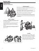
Operator Safety SLOPE OPERATION Safety Operation on slopes can be dangerous. Using the unit on a slope that is too steep where you do not have adequate wheel traction (and control) can cause sliding, loss of steering, control, and possible rollover. You should not operate on a slope greater than a 5.4 foot rise over a 20 foot length (15 degrees). Always mow across slopes, not up and down (to maintain traction on the wheels) and avoid sudden turns or rapid speed changes.
Operator Safety RETAINING WALLS, DROP-OFFS, AND WATER Safety Retaining walls and drop-offs around steps and water are a common hazard. Give yourself a minimum of two mower widths of clearance around these hazards and hand-trim with a walk behind mower or string trimmer. Wheels dropping over retaining walls, edges, ditches, embankments, or into water can cause rollovers, which may result in serious injury, death, or drowning.
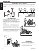
Operator Safety GENERAL OPERATION 1. Read, understand, and follow all instructions in the manual and on the unit before starting. 2. Do not put hands or feet near rotating parts or under the machine. Keep clear of the discharge opening at all times. 3. Only allow responsible adults, who are familiar with the instructions, to operate the unit (local regulations can restrict operator age). 4. Clear the area of objects such as rocks, toys, wire, etc., which could be picked up and thrown by the blade(s). 5.
Operator Safety Safety SLOPE OPERATION Slopes are a major factor related to loss-of-control and tipover accidents, which can result in severe injury or death. Operation on all slopes requires extra caution. If you cannot back up the slope or if you feel uneasy on it, do not operate on it. Control of a walk-behind or ride-on machine sliding on a slope will not be regained by the application of the brake.
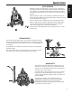
Operator Safety SERVICE AND MAINTENANCE 13. 14. 15. 16. 17. 18. 19. 20. 21. 22. 23. 24. 25. 26. Safety Safe Handling of Gasoline 1. Extinguish all cigarettes, cigars, pipes, and other sources of ignition. 2. Use only approved gasoline containers. 3. Never remove the gas cap or add fuel with the engine running. Allow the engine to cool before refueling. 4. Never fuel the machine indoors. 5.
Operator Safety Safety Safety Decals This unit has been designed and manufactured to provide you with the safety and reliability you would expect from an industry leader in outdoor power equipment manufacturing. Although reading this manual and the safety instructions it contains will provide you with the necessary basic knowledge to operate this equipment safely and effectively, we have placed several safety labels on the unit to remind you of this important information while you are operating your unit.
Operator Safety Safety Icons This unit is equipped with safety interlock switches. These safety systems are present for your safety, do not attempt to bypass safety switches, and never tamper with safety devices. Check their operation regularly. Operational SAFETY Checks Test 1 — Engine should NOT crank if: • PTO switch is engaged, OR • Parking brake is not engaged, OR • Ground speed control levers are not in the NEUTRAL position.
Features and Controls Features and Controls Identification Numbers Controls SA M PL E When contacting your authorized dealer for replacement parts, service, or information you MUST have these numbers. Record your part number, serial number and engine serial numbers in the space provided on the inside front cover for easy access. These numbers can be found in the locations shown in Figure 1. NOTE: For location of engine identification numbers, refer to the engine owner’s manual. 10 A Figure 1.
Features and Controls Controls Figure 2. Control Locations Control Functions The information below briefly describes the function of individual controls. Starting, stopping, driving, and mowing require the combined use of several controls applied in specific sequences. To learn what combination and sequence of controls to use for various tasks see the OPERATION section. Ground Speed Control Levers These levers control the ground speed of the rider.
Features & Controls Fuel Tank Cap Parking Brake To remove the cap, turn counterclockwise. DISENGAGE Releases the parking brake. Fuel Level Gauge Controls ENGAGE Locks the parking brake. Pull the parking brake lever up to engage the parking brake. Push the lever down to disengage the parking brake. NOTE: To start the unit the parking brake must be engaged. PTO (Power Take Off) Switch The PTO switch engages and disengages the mower. Pull UP on the switch to engage, and push DOWN to disengage.
Operation Operation General Operating Safety Before first time operation: • Be sure to read all information in the Safety and Operation sections before attempting to operate this tractor and mower. • Become familiar with all of the controls and how to stop the unit. • Drive in an open area without mowing to become accustomed to the unit. WARNING Never operate on slopes greater than (15°) which is a rise of 5.4 feet (1,6 m) vertically in 20 feet (607 cm) horizontally.
Operation Check Tire Pressures Tire pressure should be checked periodically, and maintained at the levels shown in the chart. Note that these pressures may differ slightly from the “Max Inflation” stamped on the side-wall of the tires. The pressures shown provide proper traction, improve cut quality, and extend tire life. Tire Pressure Front 40 psi (2,76 bar) Rear 15 psi (1,03 bar) Figure 4. Checking Tire Pressure Seat Adjustment Operation See Figure 5.
Operation Mowing Height Adjustment The cutting height adjustment pin (A, Figure 6) controls the mower cutting height. The cutting height is adjustable between 1-1/2” (3,37 cm) and 4-1/2” (11,47 cm) in 1/4” (0,64 cm) increments. C A B 1. Depress the deck lift foot pedal (B) until it locks into the 4-1/2” (11,47 cm) position. 2. Place the cutting height adjustment pin in the desired cutting height. 3. Depress the deck lift foot pedal then push the lock lever (C) toward the right to release the lock. 4.
Operation Starting the Engine WARNING Operation If you do not understand how a specific control functions, or have not yet thoroughly read the FEATURES & CONTROLS section, do so now. Do NOT attempt to operate the tractor without first becoming familiar with the location and function of ALL controls. 1.
Operation Zero Turn Driving Practice Smooth Travel The lever controls of the Zero Turn rider are responsive, and learning to gain a smooth and efficient control of the rider’s forward, reverse, and turning movements will take some practice. The lever controls of the Zero Turn rider are responsive.
Operation Practice Turning Around a Corner Practice Turning In Place While traveling forward allow one lever to gradually return back toward neutral. Repeat several times. To turn in place, “Zero Turn,” gradually move one ground speed control lever forward from neutral and one lever back from neutral simultaneously. Repeat several times. NOTE: To prevent pivoting directly on the tire tread, it is best to keep both wheels going at least slightly forward. Operation Executing Turns Figure 12.
Operation Mowing 1. Engage the parking brake. Make sure the PTO switch is disengaged, the ground speed control levers are locked in the NEUTRAL position and the operator is on the seat. 2. Start the engine (see Starting The Engine). 3. Set the mower cutting height (see Mowing Height Adjustment). 4. Set the throttle to FULL. 5. Engage the PTO by pulling up on the PTO switch. 6. Begin mowing. See Mowing Recommendations for tips on mowing patterns, lawn care, and trouble shooting information. 7.
Operation When and How Often to Mow The time of day and condition of the grass greatly affect the results you’ll get when mowing. For the best results, follow these guidelines: 1. Mow when the grass is between three and five inches high. 2. Mow with sharp blades. Short clippings of grass one inch or shorter decompose more quickly than longer blades. Sharp mower blades cut grass cleanly and efficiently, preventing frayed edges which harm the grass. 3. Mow at time of day when the grass is cool and dry.
Operation Proper Mulching Attaching A Trailer Mulching consists of a mower deck which cuts and recuts clippings into tiny particles and which then blows them down INTO the lawn. These tiny particles decompose rapidly into by-products your lawn can use. UNDER PROPER CONDITIONS, your mulching mower will virtually eliminate noticeable clippings on the lawn surface. The maximum weight of a towed trailer should be less than 200 lbs (91kg).
Regular Maintenance Regular Maintenance Maintenance Schedule The following schedule should be followed for normal care of your rider and mower. You will need to keep a record of your operating time. Determining operating time is easily accomplished by observing the elapsed time recorded by the hour meter.
Regular Maintenance Checking / Adding Fuel WARNING To add fuel: 1. Remove the fuel cap. 2. Fill the tank to about 1-1/2” (3,81 cm) of the bottom of the filler neck. This will allow for fuel expansion. NOTE: Do not overfill. Refer to your engine manual for specific fuel recommendations. 3. Install and hand tighten the fuel cap. Fuel Filter The fuel filter is located in the fuel line between the fuel tank and the carburetor, near the fuel pump. If filter is dirty or clogged, replace as follows: 1.
Regular Maintenance Lubrication Lubricate the unit at the locations shown in Figures 20 through 23 as well as the following lubrication points. Grease: • front caster wheel axles & yokes • deck lift pivot blocks • mower deck spindles • mower deck idler arm Use grease fittings when present. Disassemble parts to apply grease to moving parts when grease fittings are not installed. Figure 20. Deck Lubrication Not all greases are compatible.
Regular Maintenance Check / Fill Transmission Oil Oil Type: 20W-50 conventional detergent motor oil. 1. Check the oil level when the unit is cold. Locate the transmission oil reservoirs (A, Figure 24) located on the seat support plate. The oil should be up to the “FULL COLD” mark (B). If the oil is below this level, proceed to step 2. A 2. Before removing the reservoir caps, make sure the area around the reservoir cap and fill neck of the reservoir is free of dust, dirt, or other debris.
Regular Maintenance Servicing The Mower Blades Removing the Mower Blade CAUTION Avoid injury! Mower blades are sharp. • Always wear gloves when handling mower blades or working near blades. 1. To remove the mower blade, use a 1” wrench on the flats of the spindle shaft and remove the mower blade mounting bolt with a 15/16” wrench (Figure 26). 2. If there are no flats on the spindle shaft, wedge a wooden block between the mower blade and the mower deck housing to keep the mower blade from turning.
Regular Maintenance Sharpening the Mower Blade A CAUTION Avoid injury! Mower blades are sharp. • Always wear gloves when handling the mower blades. • Always wear safety eye protection when grinding. 1. Sharpen the mower blades with grinder, hand file, or electric blade sharpener. 2. Sharpen the mower blade by removing an equal amount of material from each end of the mower blade. 3. Keep the original bevel (A, Figure 29) when grinding. DO NOT change the mower blade bevel. 4.
Regular Maintenance Ground Speed Control Lever Adjustment The control levers can be adjusted in three ways. The alignment of the control levers, the placement of the levers (how close the ends are to one another) and the height of the levers can be adjusted. B A To Adjust the Handle Alignment Loosen the mount bolts (A, Figure 32) and pivot the lever(s) (B) to align with each other.
Regular Maintenance Parking Brake Adjustment 1. Disengage the PTO, stop the engine, engage the parking brake, and remove the key from the ignition. 2. Raise the seat plate to gain access to the parking brake components. 3. Measure the distance from the top of the brake spring rod (C, Figure 34) to the top of the lock nut (D) on both sides of the unit. The measurement should be .50” (1,27 cm). If not, adjust the locknut to achieve the measurement of .50” (1,27 cm) 4.
Regular Maintenance Return-to-Neutral Adjustment To determine if it is necessary to adjust the neutral return, perform the following steps. 1. Disengage the PTO, engage the parking brake and turn off the engine. 2. Move the ground speed control levers into the operating position, pull the levers rearward and release. 3. Move the ground speed control levers out towards the neutral position.
Regular Maintenance Deck Rod Timing Adjustment Figure 36. Check Lift Rod Timing Figure 37. Adjust Lift Rod Timing Maintenance 1. Park the machine on a flat, level surface. Disengage the PTO, engage the parking brake, turn off the engine, and remove the ignition key. Rear tires must be inflated to 15 psi (1,03 bar); front tires to 40 psi (2,76 bar). 2. To check the lift rod timing, measure and record the distance between the lift pivots and the rod pivots. Repeat for other side of unit. See Figure 36. 3.
Regular Maintenance Mower Belt Replacement - 48” Deck Models NOTICE To avoid damaging belts, DO NOT PRY BELTS OVER PULLEYS. 1. Park the tractor on a smooth, level surface such as a concrete floor. Disengage the PTO, engage the parking brake, turn off the engine, and remove the ignition key. 2. Lower the mower deck to its lowest cutting position and remove the mower deck guards. 3. Using a 1/2” breaker bar, place the square end in the square hole located in the end of the idler arm (A, Figures 40).
Regular Maintenance Hydraulic Pump Drive Belt Replacement 1. Park the tractor on a smooth, level surface such as a concrete floor. Disengage the PTO, engage the parking brake, turn off the engine, and remove the ignition key. 2. Remove the PTO drive belt (see MOWER BELT REPLACEMENT for removal instructions). 3. Loosen and remove the crankshaft bolt (C, Figure 42) and the PTO clutch (B) from the engine crankshaft.
Regular Maintenance Battery Maintenance NOTE: This unit is equipped with a maintenance-free BCIU1 battery. Cleaning the Battery and Cables WARNING A Be careful when handling the battery. Avoid spilling electrolyte. Keep flames and sparks away from the battery. When removing or installing battery cables, disconnect the negative cable FIRST and reconnect it LAST. If not done in this order, the positive terminal can be shorted to the frame by a tool. Figure 44. Battery Compartment A.
Regular Maintenance Battery Service Checking Battery Voltage WARNING Keep open flames and sparks away from the battery; the gasses coming from it are highly explosive. Ventilate the battery well during charging. A voltmeter can be used to determine condition of battery. When engine is off, the voltmeter shows battery voltage, which should be 12 volts. When engine is running, the voltmeter shows voltage of charging circuit which normally is 13 to 14 volts.
Regular Maintenance THIS HOOK-UP FOR NEGATIVE GROUND VEHICLES To Starter Switch To Starter Switch Jumper Cable Starting Vehicle Battery Discharged Vehicle Battery Jumper Cable To Ground Engine Block MAKE CERTAIN VEHICLES DO NOT TOUCH Figure 45.
Regular Maintenance Storage Temporary Storage (30 Days Or Less) Remember, the fuel tank will still contain some gasoline, so never store the unit indoors or in any other area where fuel vapor could travel to any ignition source. Fuel vapor is also toxic if inhaled, so never store the unit in any structure used for human or animal habitation.
Troubleshooting Troubleshooting Troubleshooting Chart While normal care and regular maintenance will extend the life of your equipment, prolonged or constant use may eventually require that service be performed to allow it to continue operating properly. The troubleshooting guide below lists the most common problems, their causes and remedies. See the information on the following pages for instructions on how to perform most of these minor adjustments and service repairs yourself.
Troubleshooting Rider Troubleshooting Continued. Problem Engine runs, but rider will not drive. Rider drive belt slips. Brake will not hold. Rider steers or handles poorly. Cause Remedy 1. 1. Move the transmission release lever(s) to the “closed” position. 2. See Drive Belt Replacement. 3. See problem and cause below. 4. See authorized service dealer 1. Clean as required. 2. Adjust spring tension. See Drive Belt Replacement 3. Replace belt. 1. See Brake Adjustment. 2. Replace with new brake pads. 1.
Troubleshooting Troubleshooting Common Cutting Problems Problem Cause Remedy Streaking. 1. 2. 3. 4. 5. 6. 1. Sharpen your blades. 2. Replace your blades. 3. Always mow at full throttle. 4. Slow down. 5. Clean out the mower. 6. Overlap your cutting rows. 3. 4. 5. Blades are not sharp. Blades are worn down to far. Engine speed is too slow. Ground speed is too fast. Deck is plugged with grass Not overlapping cutting rows enough. Not overlapping enough when turning. Lawn is uneven or bumpy.
Specifications Specifications NOTE: Specifications are correct at time of printing and are subject to change without notice. ENGINE: 26 HP Briggs & Stratton Make Model Horsepower Displacement Electrical System Oil Capacity Briggs & Stratton 44P777-0124-G1 26 @ 3600 rpm 44.2 Cu. in (724 cc) 12 Volt Starter, 16 amp. Alternator, Battery: 340 CCA 2.0 US qt.. (1.9 L) w/ Filter CHASSIS: Fuel Tank Rear Wheels Front Wheels Capacity: 8 Gallons (30,3 L) Tire Size: 20 x 8.
42 www.Snapper.com 2 ALIGN THIS EDGE WITH A VERTICAL SURFACE (TREE, POLE, FENCE POST, BUILDING, ETC) EGREE SLOPE OPE EE S L 15 D EGR A 10 D IS A THIS IS THIS SLOPE INDENTIFICATION GUIDE 3 COMPARE THE ANGLE OF THE FOLD TO THE ANGLE OF THE SLOPE 1. Fold this page along the dotted line indicated above. 2. Align the left edge of this guide with a vertical tree, a power line pole, a fence post, or any vertical structure. 3. Compare the angle of the fold with the angle of the hill.
Notes
Notes
ZERO-TURN RIDING MOWER Product Specifications: Common Service Parts: ENGINE: BELTS AND BLADES: 26 HP Briggs & Stratton Make Model Oil Capacity Briggs & Stratton 44P777-0124-G1 2.0 US qt. (1,9 L) w/ Filter Front Wheels Capacity: 8 Gallons (30,3 L) Tire Size: 20 x 8.00 -10 (48” Model) Inflation Pressure: 15 psi (1,03 bar) Tire Size: 11 x 4.00 - 5 Inflation Pressure: 40 psi (2,76 bar) 535 Macon St. McDonough, GA 30253 www.snapper.