OPERATOR’S MANUAL Rear Tine Tiller 6HP Rear Tine Tiller Mfg. No. Description 1694161 1694908 7800052 6016RT, 6HP Rear Tine Tiller 6016RT, 6HP Rear Tine Tiller 6016RT, 6HP Rear Tine Tiller 7HP Rear Tine Tiller Mfg. No. Description 1694162 1694909 7800053 7016RT, 7HP Rear Tine Tiller 7016RT, 7HP Rear Tine Tiller 7016RT, 7HP Rear Tine Tiller 1722732 Revision 02 Rev.
Table Of Contents MODEL IDENTIFICATION .......................................... 1 SAFETY RULES ......................................................... 2 Owner's Responsibility ............................................. 2 General .................................................................... 2 Preparation ............................................................... 2 Operation ................................................................. 3 Maintenance & Storage ...........................
Safety Rules OWNER'S RESPONSIBILITY • Safe and effective use of the rototiller is the owner's responsibility. CAREFULLY READ THIS MANUAL AND FOLLOW ALL INSTRUCTIONS. • Be familiar with all controls before operating the tiller. Your tiller is equipped with a safety device that enables you to stop the wheels and tines quickly in an emergency. Learn how the drive safety control levers work and how to control the tiller at all times. • Never allow children to operate the tiller.
Safety Rules OPERATION • Never allow bystanders near the unit. • Never operate the tiller without guards, covers, and hoods in place. • Use only attachments and accessories approved by the manufacturer of the tiller. • Never start the engine or operate the tiller with the wheels in the free-wheel position. Make sure the wheel lockouts or lockpins are engaged through wheel hubs and wheel axle. The wheels act as a brake to keep the tiller at a controlled speed.
Safety Rules SAFETY DECALS This rototiller unit has been designed and manufactured to provide you with the safety and reliability you would expect from an industry leader in outdoor power equipment manufacturing.
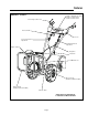
Features MODEL 7016RT* 1722551 - Simplicity Logo Decal 1723522 - 7016 RT Decal 1723523 - 6016 RT Decal Drive Safety Control Lever 7016 RT Reverse Handle Console Reverse Belt Tension Adjustment Forward Belt Tension Adjustment Engine Controls Drag Stake Detent Pin Belt Cover Wheel Lockouts (Standard on Model 7016RT) Bumper Guard (Standard on Model 7016RT) Serial No.
Controls DRIVE SAFETY CONTROL LEVERS REVERSE HANDLE Engage wheels and tines into forward, releasing returns machine to neutral. Engages wheels and tines in reverse. Pulling down on drive safety control levers engages the wheels and tines. Releasing drive safety control levers disengages the wheels and brings the tiller to a complete stop. It is now in the neutral position. Pulling reverse handle back towards operator reverses tiller.
Controls ENGINE CONTROLS Your new rototiller has been designed for both ease of use and lasting reliability, and features a simplified control system that requires just two operating controls. These two operating controls, the Choke and the Throttle, are conveniently located on the tiller engine where they can be easily adjusted to start and run the unit under a variety of operating conditions.
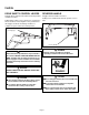
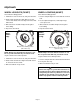
Adjustments WHEEL LOCKOUTS (7016RT) WHEEL LOCKPINS (6016RT) Place wheels in tilling position. Place wheels in tilling position. 1. Pull knob in center of wheel out, away from machine. 1. Remove lockpin. Align hole in axle with hole in wheel hub. 2. Rotate knob and lockout to align with slot on axle, release knob. Rotate wheel to align slot in wheel hub with lockout. 2. Insert lockpin through holes, fold lockpin ring to secure pin to axle. 3.
Adjustments HANDLEBAR ADJUSTMENTS Height Adjustment Pull Detent Pin for Swivel Adjustment The ideal height of the handlebar varies with operator height and the depth of tilling. To adjust handlebar height: 1. Remove bolt from lower crossbar of handlebar and pivot handlebar height adjuster. 2. Align handlebar to desired hole on the height adjuster. 3. Install bolt and retighten. 3 Height Adjustment Positions Swivel Adjustment Handlebar swivels 20° left or right for operator comfort.
Adjustments DEPTH REGULATOR LEVER BELT TENSION ADJUSTMENT Tilling depth is controlled by the height of the depth regualtor lever. Proper belt tension is critical to good performance. After 1/2 hour of operation, all cables may have to be adjusted due to initial stretch. Thereafter, check tension after every 2 hours of operation. To adjust tilling depth. 1. Remove detent pin. To increase belt tension: 2. Raise the depth regulator lever to position tines at chosen tilling depth. 1.
Operation PRE-START INSPECTION 1. Make sure all safety guards are in place and all nuts and bolts are secure. 2. Check oil level in engine crankcase. See your engine manual for procedure and specifications. 3. Inspect air cleaner for cleanliness. See your engine manual for procedure. ENGINE IS SHIPPED FROM FACTORY WITHOUT OIL. YOU MUST ADD ENGINE OIL BEFORE STARTING ENGINE. START-UP 4. Check the fuel supply. Fill the fuel tank no closer than 1 inch from top of tank to provide space for expansion.
Operation WARNING Temperature of muffler and near by areas may exceed 150°° F. Avoid these areas. WARNING Do not move choke control to CHOKE to stop engine. Backfire or engine damage may occur. TILLING 1. Adjust the depth regulator lever to desired tilling depth. NOTE: Raise depth regulator lever up one hole at a time, testing tiller operation after each raise. Raising depth regulator lever too high can result in loss of control of tiller! 2. Move the throttle control to fast. 3.
Tips TILLING TIPS WARNING Extreme caution must be taken in selecting tilling depth. If you attempt to till too deeply for soil conditions, that is, with the drag stake in too high a position, loss of control could result. The key to successful tilling is to begin with a shallow cut on the first pass, and then work an inch or two deeper on each successive pass. ✮ Tilling depth will vary with ground conditions.
Normal Care SCHEDULE Your rototiller has been designed and produced by the industry's leading manufacturer of outdoor power equipment to provide you with years of reliable operation. Keeping your tiller in top running condition will prolong its life, and help you obtain optimum performance whenever you wish to till your garden. Please read this normal care schedule, and observe these recommended care operating intervals to extend the life of your unit.
Normal Care SERVICING THE ROTOTILLER WARNING General The following information will help you make the necessary checks and perform the procedures required to follow the normal care recommendations made for your rototiller unit. If you prefer, your local authorized dealer can make these checks and perform the required procedures for you.
Normal Care Change Forward/Reverse Belt 1. Turn off engine. Engine must be cool. 2. Remove spark plug wire and secure from spark plug. 3. Remove belt guard. ✮ remove the forward belt from the forward engine pulley: - gently pull the engine recoil rope to rotate the pulley. - with the pulley turning, force the forward belt out of the V-groove. - slide the belt free of the engine pulley. - pull the forward belt down and out of the way.
Normal Care CAUTION Do not operate tiller before reading the engine manual provided in the parts packet. WARNING Temperature of muffler and near by areas may exceed 150°° F. Avoid these areas. Engine can overheat and become damaged if debris blocks the cooling system or rotating screen. Engine is shipped from factory without oil. You must add engine oil before starting engine. Check or Fill Oil Sump 1. Add oil according to engine manual. Do not overfill. Use a clean, high quality detergent oil.
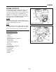
Normal Care Check Tiller Transmission Grease Check Tire Pressure Recommended tire pressure is 20 PSI. If tires do not have equal pressure, tiller will pull to one side. Lubrication TILLER TRANSMISSION IS SHIPPED FROM FACTORY WITH THE PROPER AMOUNT OF 00 LIQUID GREASE. Proper lubrication of moving mechanical parts of your rototiller is a very important part of care and maintenance. You should oil the moving parts shown at 10 hour intervals using a 30 weight oil. Check the grease level annually.
Storage PREPARE FOR STORAGE Follow the steps below to prepare your tiller for storage. Read your engine manual for detailed instructions on preparing the engine for storage. 1. Protect wheels and axles from rust: - Loosen locking bolt inside wheel. Slide wheel toward machine. - Coat the axles lightly with axle grease. - Move wheel back into position and snug locking bolt. Back off locking bolt 1/16 turn and lock jam nut. 2.
Troubleshooting and Repair TROUBLESHOOTING GUIDE While normal care and routine maintenance will extend the life of your rototiller, prolonged or constant use may eventually require that service be performed to allow it to continue operating properly. The troubleshooting guide below lists the most common problems, causes and remedies. WARNING Practice safety at all times.
Troubleshooting and Repair PROBLEM REMEDY/ACTION Belts squeal in neutral and/or reverse • Adjust forward belt guide: - turn engine off and allow muffler to cool - disconnect spark plug wire and secure from spark plug - remove belt guard - pull down on drive safety control levers - manually bend forward belt guide so there is 1/16 inch or less clearance between belt guide and belt - replace belt guard and spark plug wire Belts squeal in forward operation • Adjust tabs on the reverse belt guide - turn en
Specifications FEATURES N 7-HP Briggs & Stratton Engine (7016RT) N 6-HP Briggs & Stratton Engine (6016RT) N Tractor Type Pneumatic Tires N All Gear Drive Transmission N Handlebar Height Adjustment N Forward/Reverse Control N Functional Depth Regulator System N Wheel Lockout Control (7016RT) N Wheel Lockpins (6016RT) N Drive Safety Control Levers N Self Cleaning Bolo Tines (7016RT) N Double Bolo Tines (6016RT) N Bumper Guard (7016RT) N Hiller-Furrower Attachment (7016RT) Technical Manuals Additional copies
MANUFACTURING, INC. 500 N Spring Street / PO Box 997 Port Washington, WI 53074-0997 www.SimplicityMfg.com Snapper Inc. 535 Macon Street McDonough, GA 30253 www.snapper.com © Copyright 2005 Simplicity Manufacturing, Inc. All Rights Reserved. Printed in USA.