R N ep o ro t fo du r ct io n OPERATOR’S MANUAL Rear Tine Tiller 8.5 TP Rear Tine Tiller Mfg. No. Description 1695583 1695577 6016RT, 8.5 TP Rear Tine Tiller 6016RT, 8.5 TP Front Tine Tiller 1737349 Revision A Rev.
N ep o ro t fo du r ct io n R
Table of Contents 3 4 4 4 4 4 5 5 6 7 Unpack Tiller ............................................................ 7 Attach Handlebar to Tiller ........................................ 7 Fill Engine Crankcase .............................................. 7 FEATURES ................................................................ 8 MAINTENANCE ...................................................... 15 Maintenance Schedule .......................................... 15 Servicing the Rototiller .................
Safety Rules OWNER’S RESPONSIBILITY ! DANGER Accurate assembly and safe and effective use of the rototiller is the owner’s responsibility. s Read and follow all safety instructions. s Carefully follow all assembly instructions. s Maintain the tiller according to directions and schedule included in this Earthquake operator’s manual. s Ensure that anyone who uses the tiller is familiar with all controls and safety precautions.
Safety Rules c. Fill fuel tank outdoors with extreme care. Never fill fuel tank indoors. IMPORTANT THE RIGHT AND LEFT SIDES OF YOUR ROTOTILLER ARE DETERMINED FROM THE OPERATING POSITION AS YOU FACE THE DIRECTION OF FORWARD TRAVEL. ENGINE IS SHIPPED FROM FACTORY WITHOUT OIL. YOU MUST ADD ENGINE OIL BEFORE STARTING ENGINE. d. Replace gasoline cap securely and clean up spilled fuel before restarting. s Never attempt to make any adjustments while the engine is running.
Safety Rules SAFETY DECALS This rototiller unit has been designed and manufactured to provide you with the safety and reliability you would expect from an industry leader in outdoor power equipment manufacturing.
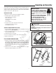
Unpacking and Assembly Your rototiller comes fully assembled except for a few parts. The following instructions will help you unpack your tiller and assemble and adjust your tiller’s depth regulator lever, cable tension and handlebar height. You will need 2- 9/16” wrenches. UNPACK TILLER 1. Open top of carton and remove handlebar assembly. IMPORTANT THE RIGHT AND LEFT SIDES OF YOUR ROTOTILLER ARE DETERMINED FROM THE OPERATING POSITION AS YOU FACE THE DIRECTION OF FORWARD TRAVEL.
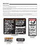
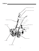
Features forward drive safety control lever reverse drive safety control lever bumper guard N ep o ro t fo du r ct io n forward & reverse cable depth regulator lever detent pin R belt guard wheel lock pin recoil start serial number plate 8
Operation PRE-START INSPECTION ! CAUTION 1. Make sure all safety guards are in place and all nuts and bolts are secure. 2. Check oil level in engine crankcase. See your engine manual for procedure and specifications. 3. Inspect air cleaner for cleanliness. See your engine manual for procedure. 4. Check the fuel supply. Fill the fuel tank no closer than 1 inch from top of tank to provide space for expansion. See your engine manual for fuel recommendations. 5.
Operation IDLE SPEED Use the “low” position on the throttle lever to reduce stress on the engine when tilling is not being performed. Lowering the engine speed to “idle” will help extend the life of the motor, as well as conserve fuel and reduce the noise level of the equipment. OPERATING SPEED For normal tilling, set the throttle lever to “fast”. SHUTTING DOWN To stop the engine at any time, move throttle control to the off position.
Operation DRIVE SAFETY CONTROL LEVERS ! CAUTION FORWARD LEVER DO NOT OPERATE BOTH “FORWARD” AND “REVERSE” DRIVE SAFETY CONTROL LEVERS AT THE SAME TIME. Engages wheels and tines into forward. Pulling the drive safety control lever labeled (FORWARD) toward the handlebar engages the wheels and tines. Releasing the lever stops the wheels and tines and brings the tiller to a complete stop. THIS INFORMATION IS PROVIDED HERE ONLY TO INTRODUCE THE CONTROLS. DO NOT START THE ENGINE AT THIS TIME.
Operation WHEEL LOCK PINS ! WARNING Place wheels in tilling position. 1. Remove lock pin. Align hole in axle with hole in wheel hub. (SEE FIGURE 2) 2. Insert lock pin through holes, fold lock pin ring to secure pin to axle. 3. Firmly lock wheel and axle together before tilling. NEVER START ENGINE OR OPERATE TILLER WITH WHEELS IN FREE-WHEEL POSITION.
Operation DEPTH REGULATOR LEVER Tilling depth is controlled by the height of the depth regulator lever. ! WARNING DO NOT ADJUST TILLING DEPTH UNLESS DRIVE SAFETY CONTROL LEVERS ARE RELEASED TO NEUTRAL POSITION. To adjust tilling depth. (SEE FIGURE 4) 1. Remove detent pin. 2. Raise the depth regulator lever to position tines at chosen tilling depth. 3. Align hole in depth regulator lever with hole in depth regulator bracket and replace detent pin.
Operation TILLING TIPS ! WARNING The key to successful tilling is to begin with a shallow cut on the first pass, and then work an inch or two deeper on each successive pass. s 4ILLING depth WILL vary WITH gROUND CONDITIONs. s 7HEN BEGINNING to TILL IN UNBROkEN gROUND or IN eXTREMELY hard SOIL set the DETENT PIN IN the HIGHEST HOLE of the drag stake (fOLLow INSTrUCTIONS UNDER 4ILLING SECTION . 4HIS WILL ALLow for SHALLow TILLING.
Maintenance MAINTENANCE SCHEDULE Your rototiller has been designed and produced by the industry’s leading manufacturer of outdoor power equipment to provide you with years of reliable operation. Keeping your tiller in top running condition will prolong its life, and help you obtain optimum performance. Please read this normal care schedule, and note the recommended care operating intervals to extend the life of your unit.
Maintenance CHANGE FORWARD/REVERSE BELT ! CAUTION 1. Turn off engine. Engine must be cool. DO NOT OPERATE TILLER BEFORE READING THE ENGINE MANUAL PROVIDED IN THE PARTS PACKET. 2. Remove spark plug wire and secure from spark plug. 3. Remove belt guard. s REMove the forward belt from the forward engine pulley: - gently pull the engine recoil rope to rotate the pulley. ! WARNING - with the pulley turning, force the forward belt out of the V-groove.
Maintenance ENGINE MAINTENANCE Refer to the engine manual included in your parts packet for information on engine maintenance. Your engine manual provides detailed information and a maintenance schedule for performing the following tasks: 1. Check oil level before each use or after every 8 hours of operation. 2. Change oil after first 5-8 hours of operation. Change oil while engine is warm. Refill with new oil of recommended grade. 4. Check spark plug yearly or every 100 hours of operation.
Maintenance LUBRICATION Proper lubrication of moving mechanical parts is critical for proper care and maintenance. Oil the moving parts at 10 hour intervals using a 30 weight oil. CLEAN TINE AXLE SHAFT 1. Turn off engine. Engine must be cool. 2. Remove spark plug wire and secure from spark plug. ! WARNING DO NOT STORE TILLER IN AN UNVENTILATED AREA WHERE FUEL FUMES MAY REACH FLAME, SPARKS, PILOT LIGHTS OR AN IGNITED OBJECT. DRAIN FUEL OUTDOORS AWAY FROM ANY IGNITION SOURCES.
Maintenance TROUBLESHOOTING GUIDE ! WARNING While normal care and routine maintenance will extend the life of your rototiller, prolonged or constant use may eventually require that service be performed to allow it to continue operating properly. The troubleshooting guide below lists the most common problems, causes and remedies. PRACTICE SAFETY AT ALL TIMES. ENGINE MUST BE TURNED OFF AND ALLOWED TO COOL, AND SPARK PLUG WIRE MUST BE DISCONNECTED AND SECURED BEFORE ATTEMPTING ANY MAINTENANCE OR REPAIR.
Maintenance PROBLEM REMEDY/ACTION s Adjust forward belt guide: - turn engine off and allow to cool - disconnect spark plug wire and secure from spark plug - remove belt guard - pull down on drive safety control levers - manually bend forward belt guide so there is 1/16 inch or less clearance between belt guide and belt - replace belt guard and spark plug wire Belts squeal in forward operation s Adjust tabs on the reverse belt guide to cool - turn engine off and allow - disconnect spark plug wire and secu
Technical Manuals Additional Technical Literature Available Additional copies of this manual are available, as well as fully illustrated parts lists. These manuals show all of the product’s components in exploded views (3D illustrations which show the relationship of parts and how they go together) as well as part numbers and quantities used. Important assembly notes and and torque values are also included. R N ep o ro t fo du r ct io n Technical manuals can be downloaded from: www.simplicitymfg.com www.
N ep o ro t fo du r ct io n R
N ep o ro t fo du r ct io n R
N ep o ro t fo du r ct io n R www.simplicitymfg.com www.snapper.com Briggs & Stratton Power Products Group, L.L.C. Copyright © 2008 Briggs & Stratton Corporation Milwaukee, WI USA. All Rights Reserved www.BRIGGSandSTRATTON.