ATTACHMENT OPERATOR’S MANUAL Clean Sweep Twin Catcher Clean Sweep Twin Catcher Mfg. No. 1694498 Description Clean Sweep Twin Catcher 1726793 Rev. 02 Rev.
Table of Contents Safety Rules & Information General Warnings............................................2 Safety Decals ..................................................2 Storing the Grass Catcher ...............................3 Initial Collector Assembly Install Cover & Bags ......................................13 Normal Removal & Installation Removing the Grass Catcher ........................14 Installing the Grass Catcher ..........................
Safety Rules & Information Read these safety rules and follow them closely. Failure to obey these rules could result in loss of control of unit, severe personal injury or death to you, or bystanders, or damage to property or equipment. The triangle in text signifies important cautions or warnings which must be followed. GENERAL WARNINGS • Know the unit’s controls and how to stop quickly. READ THE OPERATOR’S MANUALS. • Read and obey all safety decals.
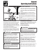
General Operating Instructions BEFORE OPERATION Clear the lawn of all sticks, stones, wire and other debris which may be caught or thrown by the mower blades. Check grass condition. If wet, wait until later in the day. If grass is wet, the grass catcher is likely to become plugged. For efficient bagging, air circulation under the mower deck, through the chute and into the bag is very important.
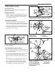
Initial Turbo Installation Torque to 55-70 ft. lbs. 12 11 44" 49 24 35 25 10 18 1 50" 18 17 2 19 20 33 1 16 3 27 2 4 7 Existing Pulley & Spacer 23 15 48 26 22 8 9 29 21 14 8 13 36 32 31 37 30 6 22 38 39 5 Existing Hardware 27 45 47 46 27 34 27 8 17 38 44 22 43 28 42 Existing Hardware (Bolt, Washer, Lockwasher, & Nut) 41 40 Ref. Qty.
Initial Turbo Installation TURBO INSTALLATION Remove Mower Deck Remove the mower deck from the unit (see Operator’s Manual for instructions). A Deflector Removal 1. Remove and retain the carriage bolts, washers, lockwashers, and nuts (A, Figure 3) holding the deflector rod to the deck. Remove and discard the deflector rod. Retain the deflector. Figure 3. Remove Deflector A. Carriage Bolts, Washers, Lockwashers, & Nuts Install Discharge Baffle B 1.
Initial Turbo Installation Install Deflector B 1. See Figure 6. Drill four 13/64” holes from the bottom of the deflector at the pre-molded drill points (A, bottom of deflector). 2. Attach the deflector to the support rod wire-form using four #10-14 x 3/4 truss head screws and nylock nuts. A C Figure 6. Install Deflector A. 13/64 Hole Locations B. Nylock Nuts C. Screws, #10-24 x 3/4 Install Belt Guide 50” Models 1. See Figure 7 & 8. Locate the taptite screw that will be replaced by capscrew (C).
Initial Turbo Installation B E Torque to 55-70 ft. lbs. D E D Original Pulley and Spacer F C B A A C Figure 9. Install Idler Assembly A. Idler Assembly. B. Belt Guide C. Capscrew, 5/16-18 x 7/8 Install Idler Assembly & Belt D. Locknuts, 5/16-18 Figure 10. Install Turbo Drive Pulley E. Taptite Screws A. Original Pulley & Spacer D. Spring Washer B. Spacer, W/Groove(New) E. Sleeve Nut C. Pulley (New) F. Spacer (New) Cover 1. See Figure 9. Remove and discard the two taptite screws from locations (E).
Initial Turbo Installation B t el er ov C 50" C B A B 44" D A E Figure 13. Belt Cover Plates A. Belt Cover Plate for 50” Mower B. Belt Cover Plate for 44” Mower F WARNING Figure 14. Install Belt Cover Plate A. Belt Cover Latch E. Support Bracket B. Belt Cover Plate F. Nylock Nut, 5/16 C. Capscrew, 5/16-18 x 1 D. Washer, 5/16 When the turbo blower assembly is removed from the mower deck, the deflector MUST be properly installed. Install Belt Cover Plate 1.
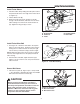
Initial Turbo Installation Install Turbo Blower D E 1. Install the turbo unit by sliding the turbo pivot rod into the pivot bracket at the front edge of the mower deck (A, Figure 17). C 2. Tilt the deflector UP (B). B 3. Rotate the turbo unit (C) into position on the discharge of the mower deck, and “latch” the slot in the turbo housing over and onto the anchor bracket at (D). Tighten the wing nut (E) to secure. A Figure 17. Install Turbo Blower A. Pivot Bracket B. Deflector C. Turbo D.
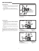
Initial Counter Balance & Weight Carrier Installation B A. B. C. D. E. F. G. H. I. J. K. L. M. D C A E L F I M J G H Rear Deck Lift Lever Trunnion (Existing) Hair Pin (Existing) Spacer, Spring (New) Spring (New) Washer (New) Plate, Spring Support (New) Spacer (Existing) Eyebolt (Existing) Washer (Existing) Capscrew (Existing) Nut (Existing) Mower Deck K Figure 1. Counter Balance Installation COUNTER BALANCE & WEIGHT CARRIER INSTALLATION Counter Balance Installation C C A B G 1.
Initial Hitch & Tube Installation G B D E A C H C A D G F C Figure 1. Install Hitch Plate A. Hitch Plate B. Heat Shield C. Capscrews, 1/2-13 x 1-1/4 D. Locknuts, 1/2-13 D B E. Upper & Lower Bumper F. Washer G. New Holes, 17/32” H. Existing RH Holes Figure 2. Install Hitch Assembly A. Horizontal Support C. Nut, 3/8-16 B. Capscrew, 3/8-16 x 3/4 D. Back Plate HITCH & TUBE INSTALLATION Install Hitch Plate and Back Plate A 1.
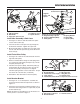
Initial Hitch & Tube Installation A A. B. C. D. E. F. G. H. D Upper Tube Middle Tube Lower Tube Nut, Nylock, 10-24 x 3/4 Washer Screw, Truss Head, 10-24 Holes Clip and Hardware E B D E F C G F H Figure 4. Assemble Tubes & Deflector A H G F Assemble Tubes & Deflector 1. Insert the lower tube (C, Figure 4) into middle tube (B). Secure the tubes as shown in Figure 4 using #10-24 x 3/4 screws, washer (E) and #10-24 nuts (D). Insert middle tube (B) into upper tube (A).
Initial Collector Assembly COLLECTOR ASSEMBLY Install Cover and Bags C B A 1. Hang the bags (F, Figure 7) on the horizontal support. Note: If desired, the bags can be lined with 30 gallon trash bags for easy disposal. 2. Install the handle (B) inside the cover. Secure with two #10-32 x 1/2 screws (C) and nuts (A). 3. Rest the cover assembly (D) on the bags (F). 4. Install the two hinge pins (E) and secure with hair pin clips (G). D 5. Open the cover and fasten cable (A, Figure 8) to support (B).
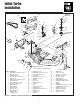
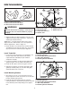
Normal Removal & Installation A. B. C. D. E. F. Tubes Hair Pin Clip Bags Clevis Pin Cover Clip E A D B C F Figure 9. Normal Removal & Installation WARNING A OPERATION WITHOUT TURBO & CATCHER For operation without turbo, the mower deflector MUST be properly installed in the down position and retained by the spring latch (See Turbo Operator’s Manual). C B NORMAL REMOVAL & INSTALLATION Removing the Grass Catcher 1. Disconnect the tubes (A, Figure 9) from the turbo and remove them from the catcher.
Removing and Reattaching Grass Catcher Installing the Grass Carcher 1. Set the back plate & support (A, Figure 11) on pins of hitch plate (C). Secure with rod (D) and hair pin (B). A 2. Install the bags (C, Figure 12). C 3. Install the cover (E, Figure 12). Secure with the clevis pins (F) and hair pin clips (B). NOTE: Push the hair pin clips all the way on or they will be bent by the hinge when the cover is opened. B 4. Connect the cover cable (Figure 8). 5.
Hardware Identification & Torque Specifications Common Hardware Types Torque Specification Chart Hex Head Capscrew FOR STANDARD MACHINE HARDWARE (Tolerance ± 20%) Washer Hardware Grade Lockwasher Carriage Bolt No Marks SAE Grade 2 Hex Nut Size Of Hardware Standard Hardware Sizing 8-32 8-36 10-24 10-32 1/4-20 1/4-28 5/16-18 5/16-24 3/8-16 3/8-24 7/16-14 7/16-20 1/2-13 1/2-20 9/16-12 9/16-18 5/8-11 5/8-18 3/4-10 3/4-16 7/8-9 7/8-14 1-8 1-12 When a washer or nut is identified as 1/2”, this is the
MANUFACTURING, INC. 500 N Spring Street / PO Box 997 Port Washington, WI 53074-0997 www.simplicitymfg.com © Copyright 2004 Simplicity Manufacturing, Inc. All Rights Reserved. Printed in USA.