Safety Instructions & Operator’s Manual for 21” STEEL DECK WALK MOWERS COMMERCIAL MODELS SERIES 18 PROPELLED MODELS CP216018KWV CRP216018KWV CP215518HV MODEL NUMBER EXPLANATION C R P 21 60 18 KW V MODEL DESIGNATION RECYCLING MODEL SELF-PROPELLED ENGINE DESIGNATION SERIES DESIGNATION ENGINE HORSE POWER * CUTTING WIDTH C – Commercial Model P – Self Propelled Model R – Recycling Model 21 – 21” Cutting Width 55 – 5.5 HP (Engine Horse Power) 60 – 6.
IMPORTANT SAFETY INSTRUCTIONS WARNING: This powerful cutting machine is capable of amputating hands and feet and can throw objects that can cause injury and damage! Failure to comply with the following SAFETY instructions could result in serious injury or death to the operator or other persons. The owner of the machine must understand these instructions and must allow only persons who understand these instructions to operate machine.
IMPORTANT SAFETY INSTRUCTIONS SAFE HANDLING OF GASOLINE OPERATION (Continued From Previous Page) 3. DO NOT remove fuel cap or add fuel with the engine running. Allow the engine to cool before refueling. 4. DO NOT refuel the machine indoors. 5. DO NOT store the machine or fuel container inside where there is an open flame, spark or pilot light such as on a water heater or other appliances. 6. DO NOT fill fuel containers inside a vehicle or on a truck or trailer bed with a plastic liner.
IMPORTANT SAFETY INSTRUCTIONS MAINTENANCE AND STORAGE (Continued From Previous Page) 9. Mower blades are sharp and can cut. Wrap the blades or wear heavy leather gloves and use CAUTION when handling them. 10. DO NOT test for spark by grounding spark plug next to spark plug hole; spark plug could ignite gas exiting engine. 11. Have machine serviced by an authorized SNAPPER dealer at least once a year and have the dealer install any new safety devices. 12.
TABLE OF CONTENTS IMPORTANT SAFETY INSTRUCTIONS...................................................................... 2 - 4 TABLE OF CONTENTS......................................................................................................5 SECTION 1 - FAMILIARIZATION.......................................................................................6 SECTION 2 - OPERATING INSTRUCTIONS............................................................... 7-11 Pre-start Checklist.............................
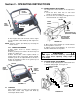
Section 1 - FAMILIARIZATION ENGINE SPEED CONTROL BLADE CONTROL WHEEL DRIVE CONTROL GROUND SPEED CONTROL CHOKE FAST ENGINE SPEED CONTROL SLOW ROPE START HANDLE OIL FILL AND DIPSTICK FUEL FILL GRASS BAG REAR HEIGHT ADJUSTMENT LATCH GRASS BAG ADAPTER FRONT HEIGHT ADJUSTMENT LATCHES FIGURE 1.1 1.1 INTRODUCTION This manual has been prepared for the operators of the SNAPPER WALK BEHIND MOWERS.
Section 2 - OPERATING INSTRUCTIONS 2.1 PRE-START CHECK LIST Make the following checks and perform the service required before each start-up. 2.1.1. Check guards, deflectors, grass bag, adapter and covers to make sure all are in place and securely tightened. 2.1.2. Check blade control, wheel drive control, and engine speed control to insure they work freely. See Figure 2.1. 2.1.6. Clean exterior surfaces of cutting deck and engine of any accumulation of spilled fuel, dirt, grass, oil, etc.
Section 2 - OPERATING INSTRUCTIONS 2.4 HANDLE HEIGHT ADJUSTMENT The height of the mower handle can be adjusted as follows: 1. Loosen the three lower nuts on each lower handle as shown in Figure 2.6. 2. Loosen the one nut securing each upper brace to the lower handle. See Figure 2.6. BLADE CONTROL HIGHER LOWER HANDLE ROPE START HANDLE ENGINE SPEED CONTROL LOWER LOOSEN BRACE NUT (BRACE NOT SHOWN) FIGURE 2.4 LOOSEN LOWER NUTS ON EACH LOWER HANDLE 5.
Section 2 - OPERATING INSTRUCTIONS 2. Set all wheels at the same cutting height. The highest cutting position is Notch 6. The lowest cutting position is Notch 1. See Figures 2.7 & 2.8. STEP 1a (Kawasaki only): Attach Bag Adapter Standoff between rope guide pulley assembly and engine recoil. See Figure 2.10. A. Remove right rear bolt from engine recoil cover. B. Remove torx screw and nut securing rope guide pulley to bracket on bag adapter. C.
Section 2 - OPERATING INSTRUCTIONS WARNING DO NOT attempt any maintenance, adjustments or service with engine and blade running. STOP engine and blade. Disconnect spark plug wire and secure away from spark plug. Engine and components are HOT. Avoid serious burns, allow sufficient time for all components to cool. 2.8 INSTALLATION of GRASS CATCHER (Slide Closure Type) Position grass bag between handles. Install grass catcher by sliding connector over flange of adapter.
Section 2 - OPERATING INSTRUCTIONS WARNING RECYCLING COVER DO NOT attempt any maintenance, adjustments or service with engine and blade running. STOP engine and blade. Disconnect spark plug wire and secure away from spark plug. Engine and components are HOT. Avoid serious burns, allow sufficient time for all components to cool. 2.10 INSTALLATION of DISCHARGE DEFLECTOR (Optional accessory on some models) Install discharge deflector if discharging is desired.
Section 3 – MAINTENANCE 3.1 INTRODUCTION To retain the quality of the mower, use genuine SNAPPER replacement parts only. Contact a local SNAPPER dealer for parts and service assistance. For the correct part or information for a particular mower, always mention model and serial number. REMOVE OIL CAP WARNING DO NOT attempt any maintenance, adjustments or service with engine and blade running. STOP engine and blade. Disconnect spark plug wire and secure away from spark plug. Engine and components are HOT.
Section 3 – MAINTENANCE WARNING RECOMMENDED BLADE RETAINING CAP SCREW TORQUE VALUE SHOULD BE 40 FT. LBS. DO NOT attempt any maintenance, adjustments or service with engine and blade running. STOP engine and blade. Disconnect spark plug wire and secure away from spark plug. Engine and components are HOT. Avoid serious burns, allow sufficient time for all components to cool. Wear heavy leather gloves when handling or working around cutting blades. Blades are extremely sharp and can cause severe injury.
Section 4 - REPAIR & ADJUSTMENTS 2. Replace the blade if it is badly chipped, bent, noticeably out of balance or has cracks or notch in either tip. See Figure 4.1 & 4.1A. Replace with new blade. WARNING DO NOT attempt any maintenance, adjustments or service with engine and blade running. STOP engine and blade. Disconnect spark plug wire and secure away from spark plug. Engine and components are HOT. Avoid serious burns, allow sufficient time for all components to cool.
Section 4 - REPAIR & ADJUSTMENTS WARNING CLUTCH CABLE DO NOT attempt any maintenance, adjustments or service with engine and blade running. STOP engine and blade. Disconnect spark plug wire and secure away from spark plug. Engine and components are HOT. Avoid serious burns, allow sufficient time for all components to cool. VINYL SPRING 1/16” TO 1/8” CLEARANCE UPPER SPRING CLUTCH CABLE EYE SPRING HOOK LOWER SPRING 4. Sharpen blade on a grinding wheel at an angle of 22 to 28 degrees.
Section 4 - REPAIR & ADJUSTMENTS WARNING USE NEEDLE NOSE PLIERS TO INSTALL DRIVE SPRING DO NOT attempt any maintenance, adjustments or service with engine and blade running. STOP engine and blade. Disconnect spark plug wire and secure away from spark plug. Engine and components are HOT. Avoid serious burns, allow sufficient time for all components to cool. 4.3 DRIVEN AND DRIVE DISC SERVICE If the mower does not propel itself properly, See Figure 4.6.
Section 4 - REPAIR & ADJUSTMENTS WARNING DO NOT attempt any maintenance, adjustments or service with engine and blade running. STOP engine and blade. Disconnect spark plug wire and secure away from spark plug. Engine and components are HOT. Avoid serious burns, allow sufficient time for all components to cool. 1/8” MEASUREMENT TO OUTSIDE EDGE OF DRIVE DISC DRIVE DISC SLIDE DRIVEN DISC ASSEMBLY TOWARD OUTSIDE EDGE 4.3.3. DRIVEN DISC ADJUSTMENT (Continued From Previous Page) 2.
Section 4 - REPAIR & ADJUSTMENTS 4.3.5. Replacing Bearing In Driven Disc Assembly If the driven disc bearing fails, remove the driven disc assembly and replace bearing as follows: 1. Remove pin and washer from transfer rod, and remove end of transfer rod from hole in driven disc assembly. See Figure 4.9. 2. Using needle nose pliers, unhook the drive spring and slide the driven disc assembly off the hex shaft. See Figure 4.12. 3. Remove snap ring that secures driven disc hub to thrust plate. See Figure 4.14.
Section 4 - REPAIR & ADJUSTMENTS 4.4 BELT SERVICE On these mowers, the engine belt transmits power from engine to drive disc. The drive disc powers the poly-v belt, which engages the transmission that powers the rear wheels. Should these belts become worn, they could cause slippage, which would impair mower performance. The condition of the engine belt and poly-v belt should be checked after every 25 hours of mower operation.
Section 4 - REPAIR & ADJUSTMENTS PULLEY POSITION WARNING DO NOT attempt any maintenance, adjustments or service with engine and blade running. STOP engine and blade. Disconnect spark plug wire and secure away from spark plug. Engine and components are HOT. Avoid serious burns, allow sufficient time for all components to cool. DRIVE DISC SLOT IN END OF DRIVE DISC BOLT BUSHING 4.4.1.
TROUBLESHOOTING PROBLEM Engine Will Not Start Using Recoil Starter PROBABLE CAUSE 1. Fuel tank empty. 2. Engine needs choking. 3. Spark plug wire disconnected. 4. Fuel Shut-Off in the “OFF” position Engine Stalls or Stops 1. Blade control is released or is not being held securely After Running against handle. 2. Engine Throttle Control in “Choke” position. 3. Fuel tank empty. 4. Engine air pre-cleaner and or air cleaner dirty. 5. Spark plug defective or gap set improperly. 6.
SERVICE SCHEDULE ITEM SERVICE PERFORMED REF.
2 YEAR LIMITED WARRANTY For two (2) years from purchase date for the original purchaser's residential, non-commercial use, SNAPPER, through any authorized SNAPPER dealer will replace, free of charge (except for taxes where applicable), any part or parts found upon examination by the factory at McDonough, Georgia, to be defective in material or workmanship or both.
PRIMARY MAINTENANCE 24
PRIMARY MAINTENANCE 25
PRIMARY MAINTENANCE 26
PRIMARY MAINTENANCE 27
SNAPPER PRODUCT REGISTRATION FORM IMPORTANT: KEEP THIS INFORMATION FOR YOUR PERSONAL RECORDS (Complete the following information on your Snapper purchase) Model Number_____________________________________________________________ Serial Number _____________________________________________________________ Date of Purchase ___________________________________________________________ Retailer____________________________________________________________________ Retailer’s Phone Number ___________________________
NOTES ___________________________________________________________________ ___________________________________________________________________ ___________________________________________________________________ ___________________________________________________________________ ___________________________________________________________________ ___________________________________________________________________ ___________________________________________________________________ ______________________________
NOTES ___________________________________________________________________ ___________________________________________________________________ ___________________________________________________________________ ___________________________________________________________________ ___________________________________________________________________ ___________________________________________________________________ ___________________________________________________________________ ______________________________
NOTES ___________________________________________________________________ ___________________________________________________________________ ___________________________________________________________________ ___________________________________________________________________ ___________________________________________________________________ ___________________________________________________________________ ___________________________________________________________________ ______________________________
Safety Instructions & Operator’s Manual for 21” STEEL DECK WALK BEHIND MOWERS COMMERCIAL MODELS SERIES 18 IMPORTANT Snapper products are built using engines that meet or exceed all applicable emissions requirements on the date manufactured. The labels on those engines contain very important emissions information and critical safety warnings. Read, Understand, and Follow all warnings and instructions in this manual, the engine manual, and on the machine, engine and attachments.