Safety Instructions & Operator’s Manual for EUROPEAN REAR ENGINE RIDING MOWER SERIES 23 MODEL E2512523BVE E281223BVE E2813523BVE E331523KVE MODEL NUMBER EXPLANATION E 33 15 23 K V EUROPEAN MODEL CUTTING WIDTH ENGINE HP * E – European Model 25 – 25” Cutting Deck 28 - 28” Cutting Deck 33 – 33” cutting Deck E ENGINE OPTIONS ENGINE TYPE SERIES DESIGNATION 10 – 10.0 hp 12 - 12.0 HP 135 – 13.5 HP 15 – 15.
IMPORTANT SAFETY INSTRUCTIONS WARNING: This powerful cutting machine is capable of amputating hands and feet and can throw objects that can cause injury and damage! Failure to comply with the following SAFETY instructions could result in serious injury or death to the operator or other persons. The owner of the machine must understand these instructions and must allow only persons who understand these instructions to operate machine.
IMPORTANT SAFETY INSTRUCTIONS PREPARATION OPERATION (Continued From Previous Page) 7. Keep people and pets out of mowing area. Immediately STOP blades, STOP engine, and STOP machine if anyone enters the area. 8. Check shields, deflectors, switches, blade controls and other safety devices frequently for proper operation and location. 9. Make sure all safety decals are clearly legible. Replace if damaged. 10. Protect yourself when mowing and wear safety glasses, long pants and substantial footwear. 11.
IMPORTANT SAFETY INSTRUCTIONS TOWING MAINTENANCE 1. Tow only with a machine that has a hitch designed for towing. DO NOT attach towed equipment except at the hitch point. 2. Follow the manufacturer’s recommendation for weight limits for towed equipment and towing on slopes. 3. DO NOT allow children or others on towed equipment. 4. On slopes, the weight of the towed equipment may cause loss of traction and loss of control. 5. Travel slowly and allow extra distance to stop.
TABLE OF CONTENTS IMPORTANT SAFETY INSTRUCTIONS ........................................................................2-4 TABLE OF CONTENTS ..................................................................................................... 5 SECTION 1 - FAMILIARIZATION ...................................................................................6-8 Decals / Symbols ........................................................................................................
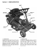
Section 1 - FAMILIARIZATION STEERING WHEEL FUEL TANK ENGINE SPEED CONTROL TRANSMISSION SHIFT LEVER IGNITION SWITCH CLUTCH/BRAKE PEDAL PARK BRAKE LATCH OVERRIDE CONTROL DISCHARGE DEFLECTOR BLADE PEDALS BLADE LEVER FIGURE 1.1 1.1 INTRODUCTION This manual has been prepared for the operator’s of the SNAPPER Rear Engine Rider. Its purpose, aside from recommending standard operating procedures and routine service requirements, is to promote SAFETY through the use of accepted operating practices.
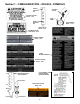
Section 1 – FAMILIARIZATION – DECALS / SYMBOLS KEY SWITCH POSITION SYMBOLS BLADE ENGAGED POSITION “ON” ON OFF START ENGINE BLADE LEVER POSITION SYMBOLS BLADE DISENGAGED POSITION “OFF” ENGINE SPEED CONTROL SYMBOLS EUROPEAN COMMUNITY 29776 CHOKE POSITION RABBIT “FAST” GUARD WARNING 29784 DO NOT operate without entire Grass Catcher or Guard in place ENGINE SPEED CONTROL EUROPEAN NOISE CONTROL 74135 PATENT NUMBERS 2-9470 TURTLE “SLOW” SERIAL NUMBER FUEL CAUTION 29113 WARNING ROTATING BLADE 22841
Section 1 – FAMILIARIZATION – DECALS / SYMBOLS LOWEST HEIGHT OF CUT TRACTION CLUTCH BATTERY CAUTION DECAL - 15691 PARK BRAKE HIGHEST HEIGHT OF CUT CLUTCH/BRAKE DECAL - 2-8514 HEIGHT OF CUT DECAL - 46218 AUTOMATIC BLADE STOP DECAL - 24072 BATTERY STORAGE DECAL - 29948 SAFETY INSTRUCTION DECAL BATTERY CAUTION DECAL - 29947 FAST TRANSMISSION SHIFT LEVER SYMBOLS CLUTCH/BRAKE, PARKING BRAKE, BLADE OPERATION MACHINE FRONT DEFLECTOR CAUTION DECAL 29839 SLOW NEUTRAL REVERSE MACHINE REAR 8
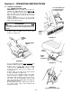
Section 2 - OPERATING INSTRUCTIONS 2.1 PRE-START CHECK LIST Make the following checks and perform the service required before each start-up. 2.1.1. Check tires and add or release air as needed to bring pressure to 12 PSI in front and 12 PSI in rear tires. 2.1.2. Check guards, deflectors and covers to make sure all are in place and securely tightened. 2.1.3. Check engine oil and add oil as needed to bring level up to the FULL mark. Refer to engine owner’s manual for oil specifications. See Figure 2.1. 2.
Section 2 - OPERATING INSTRUCTIONS 2.3 STARTING & OPERATION 2.3.1. ENGINE (ELECTRIC START) IMPORTANT: When the ignition key is turned to “START”, the engine will turn over, but will not start unless the Clutch/Brake pedal is pressed all the way down, the Blade Lever is in the “Off” position (See Figure 2.5).The operator should be in the seat. Start engine as follows: 1. Move transmission shift lever to (N) Neutral position. DO NOT start engine with transmission shift lever in a drive position.
Section 2 - OPERATING INSTRUCTIONS 4. Open vent on fuel filler cap by turning counterclockwise. NOTE: Failure to open vent on the fuel filler cap can cause engine to stall. See Figure 2.2. 5. Move engine speed control to the choke position to start a cold engine. See Figure 2.6 6. Turn key to “ON” position. See Figure 2.9. 2.3 STARTING & OPERATION 2.3.1. ENGINE (ELECTRIC START) (Continued) 8.
Section 2 - OPERATING INSTRUCTIONS WARNING WARNING Once blade is disengaged, it should come to a complete stop in 3 seconds or less. If the blade continues to rotate after 3 seconds, the blade brake must be adjusted. Refer to Section “BLADE BRAKE ADJUSTMENT” for adjustment procedures or return machine to an authorized SNAPPER dealer for adjustment. DO NOT CONTINUE to operate machine until blade brake is adjusted and functioning properly. DO NOT operate blades in reverse. STOP BLADES.
Section 2 - OPERATING INSTRUCTIONS WARNING DO NOT leave machine with engine running. Stop engine. Stop blade. Shift to neutral. Engage parking brake. Remove key. CLUTCH/BRAKE PEDAL 2.4 STOPPING - ENGINE, WHEEL DRIVE, BLADE 2.4.1. ENGINE 1. Stop engine by turning key to the “OFF” position. See Figure 2.13. TURN TO “OFF” POSITION PARK BRAKE LATCH SHOWN ENGAGED KEY FIGURE 2.14 BLADE LEVER IN “OFF” POSITION FIGURE 2.13 RELEASE BLADE PEDALS 2.4.2. WHEEL DRIVE 1.
Section 2 - OPERATING INSTRUCTIONS 2.5. CUTTING HEIGHT ADJUSTMENT 1. Adjust cutting height as desired to any one of five positions using deck lift lever. Move deck lift lever up or down to desired cutting height and then move over to secure in the height of cut notch. See Figure 2.18. 2.4 STOPPING - ENGINE, WHEEL DRIVE, BLADE 2.4.4. PARK BRAKE 1. Engage park brake by pushing clutch/brake pedal “DOWN” and moving the park brake latch to the “ENGAGED” position.
Section 2 - OPERATING INSTRUCTIONS 2.6 REVERSE LOCKOUT MECHANISM 2.6.1. Reverse Lockout Mechanism Override 1. Stop machine. Stop blade. 2. Depress and hold Override Lever. 3. Depress and hold Blade Pedals. Release Override Lever. 4. Move blade lever forward to “ON” position. Data indicates that tragic back-over accidents occur each year. These accidents usually involve unsupervised children.
Section 3 - MAINTENANCE 5. After all the oil has drained, close the drain and wipe up any oil that may have spilled. See Figure 3.1. Dispose of used oil properly. 6. Fill engine crankcase with new oil. Refer to your engine owner’s manual for oil specifications. WARNING DO NOT attempt any adjustments, maintenance, service or repairs with the engine running. Stop engine. Stop blade. Engage parking brake. Remove key. Remove spark plug wire from spark plug and secure away from plug.
Section 3 - MAINTENANCE IMPORTANT: The blade drive belt on 33” decks does not require tension adjustment. If the belt becomes worn or slack it must be replaced. Refer to Section “BLADE DRIVE BELT REPLACEMENT”. WARNING DO NOT attempt any adjustments, maintenance, service or repairs with the engine running. Stop engine. Stop blade. Engage parking brake. Remove key. Remove spark plug wire from spark plug and secure away from plug. Engine and components are HOT.
Section 3 - MAINTENANCE 3.3.1. CHECK ENGINE 1. Change engine oil. Refer to Section “CHANGE ENGINE OIL”. Refer to engine owner's manual for oil specification. 2. Change air filter. Pull up and rotate the air cleaner latch to remove cleaner cover. See Figure 3.4. 3.2.7. INTERLOCK SYSTEM SAFETY CHECKS Perform the following interlock system checks periodically during the operating season. Contact your Snapper dealer if you have questions.
Section 3 - MAINTENANCE SPINDLE GREASE FITTING 3.3 SERVICE - EVERY 25 OPERATING HOURS (Continued from previous page) WARNING DO NOT attempt any adjustments, maintenance, service or repairs with the engine running. Stop engine. Stop blade. Engage parking brake. Remove key. Remove spark plug wire from spark plug and secure away from plug. Engine and components are HOT. Avoid serious burns, allow all parts to cool before working on machine.
Section 3 - MAINTENANCE 2. To check lubricant, remove fill/level plug and visually inspect for lubricant on the internal parts of the differential. If no lubricant is visible on the internal parts of the differential, add “SNAPPER Transmission” grease as needed. See Figure 3.9. WARNING DO NOT attempt any adjustments, maintenance, service or repairs with the engine running. Stop engine. Stop blade. Engage parking brake. Remove key. Remove spark plug wire from spark plug and secure away from plug.
Section 3 - MAINTENANCE 3.5 EVERY TWO YEARS In addition to regular maintenance, the following components of the Rear Engine Rider should be carefully inspected every two years for wear or damage. Replace worn or damaged parts with genuine SNAPPER replacement parts available from an authorized SNAPPER dealer. 3.5.1. All bushings and pivot areas. 3.5.2. Check both front wheel king pins. 3.5.3. Transmission shift lever and detent. 3.5.4. Clutch disc. 3.5.5. Clutch Yoke (See Figure 4.8). 3.5.6.
Section 4 - ADJUSTMENTS & REPAIR WARNING WARNING DO NOT attempt any adjustments, maintenance, service or repairs with the engine running. Stop engine. Stop blade. Engage parking brake. Remove key. Remove spark plug wire from spark plug and secure away from plug. Engine and components are HOT. Avoid serious burns, allow all parts to cool before working on machine. Fuel Filler Cap and Vent must be closed securely to prevent fuel spillage.
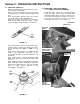
Section 4 - ADJUSTMENTS & REPAIR WARNING SLIDE FRONT END ASSMBLY DO NOT attempt any adjustments, maintenance, service or repairs with the engine running. Stop engine. Stop blade. Engage parking brake. Remove key. Remove spark plug wire from spark plug and secure away from plug. Engine and components are HOT. Avoid serious burns; allow all parts to cool before working on machine. Fuel Filler Cap and Vent must be closed securely to prevent fuel spillage. LOOSEN HARDWARE 4.2.2.
Section 4 - ADJUSTMENTS & REPAIR 2. Turn each hanger pivot the same number of rotations on the eye-bolt to raise or lower the rear of the deck. See Figure 4.6. 3. Reinstall rear hanger chains and measure blade tips again. 4. Repeat steps “1” through "3” until proper levelness is obtained. WARNING DO NOT attempt any adjustments, maintenance, service or repairs with the engine running. Stop engine. Stop blade. Engage parking brake. Remove key. Remove spark plug wire from spark plug and secure away from plug.
Section 4 - ADJUSTMENTS & REPAIR WARNING CHAIN CASE DO NOT attempt any adjustments, maintenance, service or repairs with the engine running. Stop engine. Stop blade. Engage parking brake. Remove key. Remove spark plug wire from spark plug and secure away from plug. Engine and components are HOT. Avoid serious burns, allow all parts to cool before working on machine. Fuel Filler Cap and Vent must be closed securely to prevent fuel spillage. 4.3 REAR ENGINE RIDER DRIVE COMPONENTS 4.3.1.
Section 4 - ADJUSTMENTS & REPAIR 7. Check blade balance after sharpening. If necessary, correct blade balance by grinding the heavy end of blade. 8. Reinstall blade. See Figure 4.11. Torque blade mounting bolts to recommended range of 30 to 40 ft. lbs. WARNING DO NOT attempt any adjustments, maintenance, service or repairs with the engine running. Stop engine. Stop blade. Engage parking brake. Remove key. Remove spark plug wire from spark plug and secure away from plug. Engine and components are HOT.
Section 4 - ADJUSTMENTS & REPAIR inside spindle belt guide and idler belt guide. Route belt as shown in Figure 4.14 or 4.15 10. Reinstall idler removed in Step 8. The idler belt guide tab should be positioned in the hole located on idler arm. Tighten idler pulley bolt securely. 11. Adjust belt guide. See Figure 4.14 or 4.15 for proper belt-to-belt guide clearances. 12. Check mower drive belt tension and adjust if necessary (25/28” decks only). Refer to Section “MOWER DRIVE BELT ADJUSTMENT”. 13.
Section 4 - ADJUSTMENTS & REPAIR WARNING DO NOT attempt any adjustments, maintenance, service or repairs with the engine running. Stop engine. Stop blade. Engage parking brake. Remove key. Remove spark plug wire from spark plug and secure away from plug. Engine and components are HOT. Avoid serious burns, allow all parts to cool before working on machine. Fuel Filler Cap and Vent must be closed securely to prevent fuel spillage.
Section 4 - ADJUSTMENTS & REPAIR WARNING WARNING The electrolyte (acid) produces a highly explosive gas. Keep all sparks, flame and fire away from area when charging battery or when handling electrolyte or battery. Electrolyte (acid) is a highly corrosive liquid. Wear eye protection. Wash affected areas immediately after having eye or skin contact with electrolyte (acid). Battery acid is corrosive. Rinse empty acid containers with water and mutilate before discarding.
Section 4 - ADJUSTMENTS & REPAIR 4.6.6. BATTERY TESTING Battery Condition Chart State of Charge 100% Charged w/ Sulfate Stop 100% Charged 75% Charged 50% Charged 25% Charged 0% Charged Syringe Hydrometer 1.280 1.265 1.210 1.160 1.120 Less than 1.100 Digital Voltmeter 12.80v 12.60v 12.40v 12.10v 11.90v Less than 11.80v Five Ball Hydrometer Five Balls Floating Four Balls Floating Three Balls Floating Two Balls Floating One Ball Floating Zero Balls Floating SNAPPER REAR ENGINE RIDER ACCESSORIES PART NO.
TROUBLESHOOTING PROBLEM PROBABLE CAUSE CORRECTIVE ACTION 1. Fill fuel tank with fresh fuel to proper level. 2. Move choke control to “CHOKE” position. 3. Place spark plug wire onto spark plug. 4. Contact authorized SNAPPER dealer. 5. Engage park brake. 6. Turn ignition switch to the ON position. 1. Fill fuel tank with fresh fuel to proper level. Engine Will Not 2. Move choke control to “CHOKE” position. Start Using 3. Place spark plug wire onto spark plug. Electric Starter 4.
TROUBLESHOOTING PROBLEM PROBABLE CAUSE Rider Will Not Move 1. Drive disc worn or damaged. 2. Rubber drive disc is not tracking properly on Loss Of Traction drive disc. 3. Tapered axle bolt and nut missing. 4. Axle bearing seized. 5. Insufficient lubrication in chain case or transmission/differential. Blade(s) Not Cutting 1. Blade engagement lever in the “OFF” position. 2. Mower belt slipping. 3. Cutting blade is dull, worn or damaged. 1. Uneven tire pressure. Cutting Grass Improperly 2.
MAINTENANCE SCHEDULE SUBJECT EACH USE 5 HOURS 25 HOURS 50 HOURS 100 HOURS EACH SEASON Engine SERVICE TO BE PERFORMED Check Oil Level REFERENCE PAGES Page 9 Engine Initial Oil Change Page 16 Engine Periodic Oil Change Page 18 Air Pre-Cleaner Engine Manual X** Air Cleaner Service Sponge PreCleaner Element Replace Element Engine Manual. X** Spark Plug Replace Plugs Engine Manual.
MAINTENANCE/REPLACEMENT PARTS MAINTENANCE PARTS Engine Speed Control (Briggs Engine) Engine Speed Control (Kohler Engine) Clutch/Brake Cable (25, 28” Deck Models) Clutch/Brake Cable (33” Deck Models) Brake Cable 25” Cutter Blade (Standard - Not Air Lift Compatible) 25” Cutter Blade (Standard - Air Lift Compatible) 25” Cutter Blade (Mulching) 25” Cutter Blade (Ninja - Quad Edge) 28” Cutter Blade (Standard - Not Air Lift Compatible) 28” Cutter Blade (Standard - Air Lift Compatible) 28” Cutter Blade (Mulching)
2 YEAR LIMITED WARRANTY For two (2) years from purchase date for the original purchaser's residential, non-commercial use, SNAPPER, through any authorized SNAPPER dealer will replace, free of charge (except for taxes where applicable), any part or parts found upon examination by the factory at McDonough, Georgia, to be defective in material or workmanship or both.
Safety Instructions & Operator’s Manual for EUROPEAN REAR ENGINE RIDING MOWER SERIES 23 IMPORTANT Snapper products are built using engines that meet or exceed all applicable emissions requirements on the date manufactured. The labels on those engines contain very important emissions information and critical safety warnings. Read, Understand, and Follow all warnings and instructions in this manual, the engine manual, and on the machine, engine and attachments.