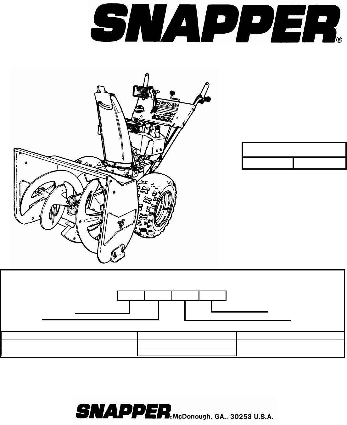
Safety Instructions & Operator’s Manual for EUROPEAN TWO STAGE LARGE FRAME SNOW THROWER SERIES 5 MODELS E9265 E11305 MODEL NUMBER EXPLANATION E 11 30 5 MODEL DESIGNATION ENGINE HP E – European Model 9 – 9.0 Engine HP (Engine Horse Power) 11 – 11.
IMPORTANT SAFETY INSTRUCTIONS WARNING: This powerful machine is capable of amputating hands and feet and can throw objects that can cause injury and damage! Failure to comply with the following instructions may result in serious injury to the operator or other persons. The owner of the snow thrower must understand these instructions and, furthermore, must allow only persons who understand these instructions to operate snow thrower.
IMPORTANT SAFETY INSTRUCTIONS OPERATIONAL PRECAUTIONS MAINTENANCE AND STORAGE (Continued From Previous Page) 7. DO NOT put hands or feet near or under rotating parts. Keep clear of the discharge opening at all times. 8. Start engine only where exhaust fumes will be safely dissipated. Allow a brief warm-up period, and practice operation of controls outside before putting the machine to work. 9. After striking a foreign object, STOP the engine (motor), remove the key, and remove the wire from spark plug.
TABLE OF CONTENTS SECTION 1 - IMPORTANT SAFETY INSTRUCTIONS.......................... 2-3 TABLE OF CONTENTS ............................................................................ 4 DECALS ............................................................................................... 5 - 6 SECTION 2 - OPERATING INSTRUCTIONS....................................... 7-12 Introduction.................................................................................................................
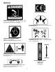
DECALS EUROPEAN COMMUNITY DANGER ROTATING IMPELLER. DO NOT use hand to unclog auger/impeller or discharge chute. Stop engine and remove key before unclogging. DISCHARGE CHUTE. Rotate control to discharge snow in desired direction. HEARING PROTECTION REQUIRED. Machine exceeds 100Lwa. 2 MAXIMUM HANDLE VIBRATION 34 M/SEC . DEADMAN CONTROLS. Depress to engage. Release to disengage/stop. Left control – wheel drive. Right control – auger/impeller. FORWARD DANGER ROTATING AUGER. Keep Away.
DECALS Read, understand & follow all manuals and instructions furnished with the Snowthrower. YEAR OF MANUFACTURE DANGER – ROTATING AUGER. KEEP AWAY. SAFETY INSTRUCTIONS TO PREVENT INJURY: 1) Read Owner’s Manual for operating and safety instructions. 2) Observe all labels and instructions. 3) DO NOT defeat safety features of controls. They are for your protection. 4) Stop engine, wait for all moving parts to stop, remove spark plug wire before unclogging or servicing machine.
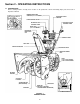
Section 2 - OPERATING INSTRUCTIONS 1.1 INTRODUCTION Before starting machine, visually check location of all operational controls and identify major parts discussed in Operator’s Manual.
Section 2 - OPERATING INSTRUCTIONS 2.1 PRE-START CHECK LIST Make the following checks and perform the service required before each start-up. 2.1.1. Check engine oil and add oil as needed to bring level up to the FULL mark. Refer to engine owner’s manual for oil specifications 2.1.2. Check guards, chutes, deflectors and covers to make sure all are in place and securely tightened. 2.1.3. Check auger/impeller control and wheel drive control to insure cables are connected and both levers operate freely.
Section 2 - OPERATING INSTRUCTIONS 2.1 PRE-START CHECK LIST 2.1.9. Check the AC electrical outlet that will be used and make sure it is a polarized outlet. The machine has a polarized plug (one blade of plug is wider than the other) that will accept a polarized extension cord. The extension cord will fit into a polarized outlet (receptacle) only one way. If plug does not fit fully into your outlet, reverse the plug.
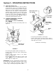
Section 2 - OPERATING INSTRUCTIONS 2.2 STARTING, OPERATION & STOPPING (RECOIL START MODELS) (Go to Page 11 for Electric Start Models) (Continued From Previous Page) AUGER/IMPELLER CONTROL WHEEL DRIVE CONTROL 2.2.2. PROPELLING SNOW THROWER IMPORTANT: This snow thrower has six forward speeds and one reverse speed. 1. Move ground speed control to the desired speed position. See Figure 2.5. 2. Proceed to Section 2.2.4. to engage wheel drive. GROUND SPEED CONTROL DEFLECTOR CONTROL CHUTE CRANK FIGURE 2.6 2.
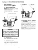
Section 2 - OPERATING INSTRUCTIONS 2.2.7. ENGINE 1. Turn fuel shut off valve to the “ON” position. See Figure 2.3. 2. Insert key into ignition switch. See Figure 2.8. 3. Connect the power cord to the starter switch box on the engine, then plug the other end into 120 volt AC receptacle for U.S.A. or 230 Volt for Europe. 4. Move choke control to the choke, “ON” position. See Figure 2.8. 2.2 STARTING, OPERATION & STOPPING (RECOIL START MODELS) 2.2.6.
Section 2 - OPERATING INSTRUCTIONS 2.2.12. FREE WHEEL MACHINE Snow Thrower can be transported without engine running and transmission drag. 1. Remove hair pins and clevis pins from both wheel axles. Remove wheels from axle. Apply a liberal amount of axle grease to the axle to allow the wheel to rotate freely. 2. Slide wheel inward toward main case. 3. Reinstall clevis pins and hair pins into outer holes to prevent wheel from sliding off of the end of axle. Wheels will rotate freely on axle.
Section 3 - MAINTENANCE 3.1 INTRODUCTION To retain the quality of the snow thrower, use only genuine SNAPPER replacement parts. Contact a local SNAPPER dealer for parts and service assistance. For the correct part or information for a particular snow thrower, always mention model and serial number. 3.3 GENERAL LUBRICATION Lubricate machine as instructed before and after operation each season. 3.3.1. GEAR CASE, AUGER SHAFT and AUGER BEARING LUBRICATION 1.
Section 3 - MAINTENANCE 3.4 ANNUALLY (END OF EACH SEASON) Perform all maintenance as described in the maintenance schedule. 3.4.1. Engine Refer to engine owner’s manual for service instructions. 3.4.2. Spark Plug Refer to engine owner’s manual for service instructions. 3.5 STORAGE PROCEDURE Refer to the Engine Owner’s Manual for directions regarding engine storage preparations. Prepare the snow thrower for “end of season” storage as follows: 1.
Section 4 - REPAIR & ADJUSTMENTS 4.1.2. AUGER BELT ADJUSTMENT (IDLER PULLEY ADJUSTMENT) NOTE: Wheel drive belt idler pulley is not adjustable. If upper cable adjustment performed in Section 4.1.1. and correct cable extension can not be accomplished, adjustment can be made at the idler pulley. All adjustment made in Section 4.1.1. will have to be reversed from the upper end of cable.
Section 4 - REPAIR & ADJUSTMENTS 6. Tilt machine forward to gain access to drive system area. Secure machine in the tilted position to prevent tipping over. Remove drive system cover plate. See Figure 4.5. WARNING Before attempting any adjustments, maintenance, service, or repairs, stop engine and auger/impeller, always remove key from ignition switch, remove spark plug wire and secure wire away from spark plug. Before tilting machine, drain all the fuel from fuel tank.
Section 4 - REPAIR & ADJUSTMENTS 6. Tilt machine forward to gain access to drive system area. Secure machine in the tilted position to prevent tipping over. Remove drive system cover plate. See Figure 4.7. WARNING Before attempting any adjustments, maintenance, service, or repairs, stop engine and auger/impeller, always remove key from ignition switch, remove spark plug wire and secure wire away from spark plug. Before tilting machine, drain all the fuel from fuel tank.
Section 4 - REPAIR & ADJUSTMENTS 4.1.5. SKID SHOE ADJUSTMENT NOTE: It is recommended to raise the auger/impeller housing when clearing rough or graveled surfaces. To raise auger/impeller the skid shoes should be lowered. 1. Tilt machine up and place a wooden block under auger/impeller housing. 2. Loosen bolts on both skid shoes. Move shoes down to raise auger/impeller housing or move skid shoes up to lower auger/impeller housing. See Figure 4.8.
Section 4 - REPAIR & ADJUSTMENTS 4.1.6. SINGLE HANDLE CONTROL ADJUSTMENT 3. To adjust, loosen the nuts on the cable guide support bracket and move the bracket in or out until the cam lock aligns with the adjusting line. Retighten nuts. 4. Hold the wheel drive control lever down to the handle bar, at the same time press the auger/impeller control lever down to the handle bar and hold in position. 5. Check the position of the cable ferrule in relation to the cam lock. The ferrule must be located 1/16” (.
Section 4 - REPAIR & ADJUSTMENTS 4.1.7. AUGER SHEAR BOLT REPLACEMENT IMPORTANT: If engine is operating correctly and auger/impeller drive belt is not damaged or severed, but the auger/impeller does not rotate it is possibly the auger/impeller shaft shear bolt. WORM GEAR 1. Remove shear bolt and nut from auger. Discard old shear bolt and nut. DO NOT reuse bolt or nut under any circumstances. Always replace existing hardware with genuine Snapper new replacement shear bolts and nuts.
TROUBLESHOOTING PROBLEM PROBABLE CAUSE Engine Will Not Start Using Recoil Starter CORRECTIVE ACTION 1. Fuel tank empty. 2. Engine needs choking and priming. 1. Fill fuel tank with fresh fuel/oil mix. 2. Move choke control to “CHOKE” position. Push primer bulb three times. 3. Place spark plug wire onto spark plug. 4. Move fuel shut off valve to the on position. 3. Spark plug wire disconnected. 4. Fuel shut off valve closed. Engine Will Not Start 1.
3 YEAR LIMITED WARRANTY For three (3) years from purchase date for the original purchaser's residential, non-commercial use, SNAPPER, through any authorized SNAPPER dealer will replace, free of charge (except for taxes where applicable), any part or parts found upon examination by the factory at McDonough, Georgia, to be defective in material or workmanship or both.
NOTES 23
Safety Instructions & Operator’s Manual for EUROPEAN TWO STAGE LARGE FRAME SNOW THROWER SERIES 5 WARNING: The engine exhaust from this product contains chemicals known to the State of California to cause cancer, birth defects or other reproductive harm. COPYRIGHT © 2000 SNAPPER INC. ALL RIGHTS RESERVED INSTRUCTION No. 7-3336 (I.R.