
User's Manual


12
Section 2 - OPERATING INSTRUCTIONS
2.2 STARTING, OPERATION & STOPPING
(ELECTRIC START MODELS)
(Go to Page 7 for Recoil Start Models)
(Continue From Previous Page)
WARNING
Objects can be thrown by the snow thrower while it
is in operation. Thrown objects could cause serious
injury to the operator or bystanders. Always wear
safety goggles or other suitable eye protection.
Keep people and pets away from area.
2.2.8. ENGAGING AUGER
1. Pull auger/impeller control lever against handle
to engage auger/impeller. See Figure 2.6.
2.2.9. ENGAGING WHEEL DRIVE
1. Move wheel drive control lever against handle
to engage wheel drive. Ground speed can be
adjusted while the machine is moving by changing
position of the ground speed control. Machine has
six forward speeds and one reverse. See Figure
2.5.
WARNING
Release auger/impeller clutch control and make sure
auger/impeller has STOPPED before rotating
discharge chute, adjusting deflector or placing hands
near auger/impeller.
2.2.10. DISCHARGE CHUTE and DEFLECTOR
ADJUSTMENT
1. Release auger/impeller control and wheel drive
control levers to allow auger/impeller and ground
speed to come to a complete stop.
2. Position the deflector to the desired location using
deflector handle located on control panel. Rotate
deflector handle counter clockwise to unlock. Push
handle to raise or pull handle to lower the deflector.
Rotate deflector handle clockwise to lock into position.
3. Rotate chute crank to position discharge chute in
desired direction. See Figure 2.5.
2.2.11. STOPPING - ENGINE, AUGER & WHEEL
DRIVE
Stop the auger/impeller and wheel drive by
releasing the auger/impeller and wheel drive
control levers. Stop the engine by moving the
engine speed control to the stop position or
removing the key from the switch. Always remove
key from key switch before leaving machine
unattended. See Figure 2.7.
2.2.12. FREE WHEEL MACHINE
Snow Thrower can be transported without engine
running and transmission drag.
1. Remove hair pins and clevis pins from both
wheel axles. Remove wheels from axle. Apply a
liberal amount of axle grease to the axle to allow
the wheel to rotate freely.
2. Slide wheel inward toward main case.
3. Reinstall clevis pins and hair pins into outer
holes to prevent wheel from sliding off of the end
of axle. Wheels will rotate freely on axle.
IMPORTANT: If engine is started the wheel drive
will not operate unless wheels and axle are
reconnected. Reinstall clevis pins and hair pins
into holes in the hubs of the wheels and through
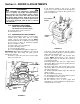
axle. See Figure 2.9.
FIGURE 2.9
OUTSIDE
(FREEWHEEL)
HOLE
INSIDE “DRIVE”
HOLE
DRIVE
WHEEL
CLEVIS
PIN
HAIRPIN