
User's Manual


8
Section 2 - OPERATING INSTRUCTIONS
2.1 PRE-START CHECK LIST
Make the following checks and perform the service
required before each start-up.
2.1.1. Check engine oil and add oil as needed to
bring level up to the FULL mark. Refer to engine
owner’s manual for oil specifications
2.1.2. Check guards, chutes, deflectors and covers
to make sure all are in place and securely
tightened.
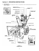
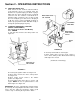
2.1.3. Check auger/impeller control and wheel drive
control to insure cables are connected and both
levers operate freely. See Figure 2.1.
IMPORTANT: On 26” & 30” Auger models only. Standing in
the operator’s position, the left handle bar lever is for wheel
drive engagement and disengagement. The right handle bar
lever is for auger/impeller engagement and disengagement.
Hold both levers down to handle bar for engagement and
release levers for disengagement. When both levers are
pressed down to the handle bar at the same time, the
operator can release the right hand lever and the right lever
will remain engaged as long as the left hand lever is held
down to handle bar. Release the left hand lever and both
levers will disengage.
FIGURE 2.1
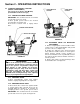
2.1.4. Check chute operation. Rotate chute crank to
insure smooth rotation throughout its range. See
Section 4.1.6. for worm gear adjustment.
2.1.5. Check tires and add or release air as needed
to bring air pressure to 12 psi without tire chains. Air
pressure with tire chains should be 16 psi.
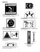
WARNING
Use approved fuel container. DO NOT smoke near
open fuel container. DO NOT fill fuel tank indoors or
when engine is running. Allow engine to cool for at
least ten minutes before refilling. Wipe off any
spilled fuel before starting engine. DO NOT run
engine indoors.
2.1.6. Add fuel to tank after pushing the machine
outside where fumes can safely dissipate. Make sure
cap is tightened after refueling. Wipe up any spilled
fuel on machine and surrounding area. Refer to
Engine Owners Manual for specifications.
2.1.7. Check auger/impeller housing and discharge
chute, both must be free of all obstructions. Clean
engine of any accumulation of spilled fuel, dirt, etc.
IMPORTANT: Electric Start Kit optional accessory
on some models.
WARNING
DO NOT use an electrical extension cord that is
damaged. A damaged electrical extension cord could
cause a shock or fire. Thoroughly inspect electrical
extension cord before using machine. If cord is
damaged, do not use and do not operate machine.
Replace damaged cord immediately. Contact your
Snapper service dealer for assistance. To reduce the
risk of electric shock, use only with an extension
cord intended for outdoor use having a cord type:
SW-A, SOW-A, STW-A, STOW-A, SJW-A, SJTW-A or
SJTOW-A.
2.1.8. Check and make sure extension cord is in
good condition. Extension cord should not have any
broken insulation or exposed wires. Use an
extension cord that is heavy enough to carry the
correct amount of current to the machine. See
Figure 2.2 for correct size to use depending on cord
length and nameplate ampere rating. If in doubt,
use the next heavier gauge cord.
MINIMUM GAUGE FOR CORD SETS
120 or 230 Volt Total Length of Cord in Feet
Rating - Amps 25 ft.
50 ft. 100 ft.
150 ft.
More
Than
Not More
Than
A.W.G.
0 6 18 16 16 14
6 10 18 16 14 12
10 12 16 16 14 12
12 16 14 12
Not
Recommended
FIGURE 2.2
PRESS BOTH LEVERS
RELEASE BLOWER
CLUTCH LEVER;
CONTINUE HOLDING
WHEEL DRIVE
WHEEL
DRIVE
CONTROL