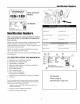
() Bimplicilq 0 A SNAPPER ® TM ATO UAL / / / / / / / / n rm_ci at_ Snowt rower 555 S Models Mfg. No. 1694587 1694595 85665 80494 860 0 Description 555M, 5HP Snowthrower, Manual Start 555M, 5HP Snowthrower, Manual Start (Export) 15225, 5HP Snowthrower, Manual Start EI5225, 5HP Snowthrower, Manual Start (Export) Models Mfg. No.
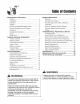
(ableofContents Safety Rules & Information Training ................................................................... 2 Preparation ............................................................. 2 Checking Tire Pressure ........................................ Operation ................................................................ Children ................................................................... 2 3 Checking Auger Gear Case Lubrication ............... 17 Lubrication ...................
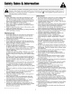
Thismachineis capableofamputating handsandfeet. Readthesesafetyrulesandfollowthemclosely. Failureto obeytheserulescouldresultin lossofcontrolofunit,severepersonalinjuryor deathto you,or bystanders, ordamageto propertyor equipment.Thetriangle,_ in text signifies important cautions or warnings which must be followed. TRAINING OPERATION 1. Read, understand, and follow all instructions on the machine and in the manuals before operating this unit.
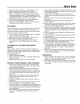
Safety Rules 21. Keep in mind the operator is responsible for accidents occurring to other people or property. 22. Data indicates that operators, age 60 years and above, are involved in a large percentage of power equipment-related injuries. These operators should evaluate their ability to operate the unit safely enough to protect themselves and others from injury. 23. DO NOT wear long scarves or loose clothing that could become entangled in moving parts. 24. Snow can hide obstacles.
Idefltificatiofl Numbers Manufacturing, Inc. Wl 53074-0997 U.S.A. North American iVlodels SERIAL 169XXXX 'io _ CE iVlodels Model Description Name/Number When contacting your authorized dealer for replacement parts, service, or information you MUST have these numbers. Record your model name/number, manufacturer's identification numbers, and engine serial numbers in the space provided for easy access. These numbers can be found in the locations shown.
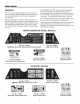
SafetyDecals GENERAL This unit has been designed and manufactured to provide you with the safety and reliability you would expect from an industry leader in outdoor power equipment manufacturing. Although reading this manual and safety instructions it contains will provide you with the necessary basic knowledge to operate this equipment safely and effectively, we have placed several safety labels on the unit to remind you of this important information while you are operating your unit.
CESaletyIcons& Compliance Specs Warning: Read Operator's Manual. Warning: Dismemberment. Read and understand the Operator's Manual before using this machine, This machine can amputate limbs. Keep bystanders and children away when engine is running. Danger: Thrown Objects. Danger: Dismemberment. This machine is capable of throwing objects and debris, Keep bystanders away, The auger can amputate limbs. Keep hands and feet away from auger and rotating parts. Warning: Remove Key Before Servicing.
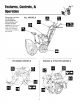
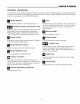
Controls,& Please take a moment and familiarize ALL MODELS yourself with the name, location, and function of these controls so that you will better understand the safety and operating instructions provided in this manual TECUMSEH MODELS BRIGGS & STRATTON MODELS
Features& Controls CONTROL LOCATIONS The information below briefly describes the function of individual controls. Starting, stopping, and driving require the combined use of several controls appfied in specific sequences, To learn what combination and sequence of controls to use for various tasks see the OPERA T!ON section, _ Speed Selector Selects forward speeds 1-5 and reverse speeds 1-2. Traction Control / Free Hand TM Fuel tank filler cap (see illustration).
EngJfle Controls STARTING CONTROLS Tecumseh L-Head Models See Figures 1 & 2 for the following instructions. Units with Optional Electric Start A. Electric Start Button - The electric start button (A) activates an electric starter mounted to the engine, eliminating the need to pull the starter handle. The electric start button operates on 120 Volts AC, which is provided by connection to the extension cord provided with units equipped with this feature.
ControJs GROUND SPEED CONTROLS A. Speed Selector - This lever (A, Figures 3 & 4) is used to set the ground speed of the snowthrower. The snowthrower has five forward speeds, 1-5, and two reverse speeds, 1-2. No neutral position or gate is required, since the traction drive design automatically provides "neutral" (no forward or reverse movement), whenever the drive control is released. B.
Operatm GENERAL OPERATION CHECKS BEFORE WARNING EACH START-UP This unit is a "two-stage" snowthrower. The first stage is the auger, which feeds the snow back into the impeller housing. The second stage is the impeller, which throws the snow out the discharge chute. If bodily contact is made with the auger or impeller when they are rotating, severe personal injury will occur. 1. Make sure all safety guards are in place and all nuts, bolts and clips are secure. 2.
Operation STARTING THE ENGINE Tecumseh Models 1. Turn the fuel valve (B, Figure 5 & 6) to the ON position. 2. Insert the engine key (F) into the engine key slot and push fully in to the RUN position. 3. Move the throttle lever (E) fully up to the FAST position. . . . Fully close the choke (G) if engine is cold. (Do not choke a warm engine.) Push the primerbutton (D) two times if engine is cold. (Do not prime a warm engine.
Operatm OPERATING THE SNOWTHROWER 1. Rotate the discharge chute to the desired direction. 2. Set the speed selector to the desired forward speed. 3. Fully press and hold the auger control (C, Figure 7) on the right-hand grip to begin auger rotation. To disengage the auger, completely release the lever. 4. Fully press and hold the traction drive control lever (B, Figure 7) on the left-hand grip to engage the traction drive and begin moving the snowthrower.
Operation DEFLECTOR Chute Deflector Knob The distance of the discharged snow is mainly controlled by the position of the deflector (Figure 9). (Engine speed also affects distance of discharge. Always operate at FULL throttle.) The more the deflector is tilted UP, the farther snow will be thrown. Loosen the deflector knob, tilt the deflector UP or DOWN, and then retighten the knob when the desired angle has been chosen. Chute Deflector Figure 9.
OperaUon FREE-WHEELING AND TRACTION DRIVE LOCK For easy turning when pushing the snowthrower, you can disengage the traction drive at one or both wheels by using the traction lock pins (See Figures 11 & 12). Klik=Pin In 1. Turn the unit off, remove the engine key, and disconnect the spark plug wire. 2. To DISENGAGE the traction drive lock, insert the traction lock pin through the outer hole in the axle. (See Figure 11). 3.
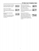
MAINTENANCE SCHEDULE MAINTENANCE REQUIRED FREQUENCY Check auger gear case lubrication.** 25 Hours Lubricate 10 Hours snowth rower. Check tire pressure. Change engine oil.*+ Clean or replace spark plug.+ Check drive linkage/belt Lubricate tension. Axle Shafts. Check/Lubricate Lubricate Monthly Free-Hand Linkage. Auger Shaft. *** NOTES Winter Weight Worm Gear Oil 10W Oil and Grease 20 psi (1.
MaJnteflaflce LUBRiCATiON \ iMPORTANT NOTE It is very important that grease fittings on the auger shaft are lubricated regularly. If auger rusts to shaft, damage to worm gear may occur if shear pins do not break. To prevent wheels rusting to axles, it is also necessary to remove the wheels and grease the axles regularly. Remove wheels and grease axles once each year. There are two grease fittings on the auger shaft. Wipe the fittings clean and apply grease, using a grease gun.
Stopage LUBRiCATiON CHECK / LUBRICATE FREE-HAND LINKAGE Check the function of the Free-Hand controls: the controis should function as described in the CONTROLS section. It is critical for the safe operation of the unit that the controls disengage when released. If the controls do not function properly, lubricate them. If lubrication does not rectify the problem, see your dealer. Under no circumstances should the unit be used if the controls are not functioning properly. IMPORTANT Figure 17.
, & Service TROU BLESHOOTING WARNING Before performing any adjustment or service to snowthrower, stop the engine and wait for moving parts to stop. Remove the key. To prevent accidental starting, disconnect the spark plug wire and fasten away from the plug. This section provides troubleshooting and service instructions. Locate the problem and check the possible cause/remedy in the order listed. Also, refer to the engine manufacturer's for additional information.
PROBLEM POSSIBLE CAUSE 1. Chute deflector too low. 1. Adjust deflector as necessary. 2. Engine speed too slow. 2. Set speed to full throttle. 3. Ground speed too fast. 4. Snowthrower discharge chute clogged. 3. Use slower speed selector setting. 4. STOP engine and REMOVE the key. DISCONNECT the spark plug wire. Clear auger using clean-out tool. See warning in SAFETY RULES. 5. Auger belt loose or worn. 5. Check auger drive belt adjustment Scraper bar does not clean hard surface. 1.
Adjustments SPEED SELECTOR PIVOT ADJUSTMENT The speed selector is factory set for optimal performance at each forward and reverse speed setting. However, if drive system components have been replaced, adjustment may be necessary. Adjust as follows: 1. Move the ground speed control (A, Figure 19) fully forward. 2. Loosen the hardware (B) securing the upper and lower shift rods. 3. Push the lower rod (C) down fully (into the housing). 4.
Adjustments MANUAL DISCHARGE CHUTE CONTROL LINKAGE ADJUSTMENT Pinion Gear Adjustment If the discharge chute is difficult to operate, first lubricate the pinion gear (A, Figure 21) and ring gear (F). If it is still difficult to operate, adjust as follows: NOTE:/f the discharge chute will not stay in position, adjust the pinion gear (A) closer to the ring gear (F). 1. Loosen the nut (G, Figure 23) which holds the pinion gear bracket in the slotted hole. 2.
Adjustments AUGER DRIVE CLUTCH ADJUSTMENT CABLE The auger drive clutch cable should be adjusted so that there is no slack in the cable when moved slightly from side to side. To adjust tension on the cable: 1. Loosen adjustment hex nut (Figure 23) by holding the adjusting flats and turning adjustment hex nut. Auger Drive / Clutch Cable 2. Tighten adjustment screw by turning adjustment flats and holding screw.
Adjustments DRIVE BELT ADJUSTMENT (Continued) If the auger drive slips (auger slows or doesn"t rotate normally while blowing snow), or stays engaged when the control is disengaged -- and the auger clutch cable has been properly adjusted -- the auger drive belt may be out of adjustment. Auger Control _ Belt Cover -----..._ WARNING Auger must NOT rotate unless the Auger Control lever has been depressed.
Adjustments & Service DRIVE BELT ADJUSTMENT Adjusting (Continued) _, Auger Belt Guide WARNING Failure to properly adjust the Auger Belt Guide may cause auger to rotate when Auger Control has not been depressed. 1. With the auger control still fully depressed, adjust the auger belt guide so that there is a 1/64" gap (1/32" Maximum) between the end of the guide and the belt (Figure 28), making certain the guide is NOT putting pressure on the belt. 2.
SBrvic6 DRIVE BELT REPLACEMENT (Cont.) WARNING Auger Drive Belt Replacement Do not go near the discharge chute or auger when the engine is running. Do not run the engine with any cover or guard removed. 1. Remove gas from fuel tank and run engine until it stops running from lack of fuel. 2. Disconnect spark plug wire and fasten it away from the spark plug. get Drive Pulley _.-"/_ 3. Remove belt cover (See Figure 25). 4.
SBrvic6 ROLLER CHAIN REPLACEMENT NOTE: This procedure does not apply to models that use an "endless" chain. Keeper link (Must install towards 1. Remove gas from fuel tank and run engine until it stops running from lack of fuel. 2. Disconnect spark plug wire and fasten it away from the spark plug. 3. Tilt the snowthrower forward and carefully rest unit on the auger end. 4. Rotate the wheel to locate the roller chain master link. wheel side with open end trailing.) 5.
NOTE: Specifications are correct at time of printing and are subject to change without notice. * Actual sustained equipment horsepower will likely be lower due to operating limitations and environmental factors. ENGINE: CHASSIS: Wheels 5 HP* Tecumseh Make Tecumseh Model Horsepower Displacement Oil Capacity Snow King 5 HP @ 3600 rpm 11.88 Cu.
Replacement Psrts& Accessories REPLACEMENT PARTS TECHNICAL Replacement parts are available from your authorized dealer. Always use genuine Simplicity / Snapper Service Parts. MAINTENANCE Additional copies of this manual are available, as well as fully illustrated parts lists. These manuals show all of the product's components in exploded views (3D illustrations which show the relationship of parts and how they go together) as well as part numbers and quantities used.
MANUFACTURING, INC. 500 N Spring Street / PO Box 997 Port Washington, Wl 53074-0997 www.simplicitymfg.com © Copyright 2004, Simplicity Manufacturing, All Rights Reserved. Printed in USA. Inc.