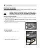
ASSEMBLY INSTRUCTIONS OPERATOR’S MANUAL PARTS LIST European Extreme Series Walk-Behind Leaf Blower Series 1 Models covered: Actual product may differ slightly from product pictured above Manual No. 7078092 (I.R.
1 preliminaries Congratulations! You have just purchased one of the finest pieces of outdoor power equipment on the market today. If properly cared for, your new blower will provide years of dependable service. Please read and follow this instruction manual carefully in order to get the most out of your new equipment.
2 safety rules regarding outdoor power equipment IMPORTANT! READ CAREFULLY THE FOLLOWING SAFETY RULES BEFORE ASSEMBLING OR OPERATING UNIT. TRAINING • Read, understand, and follow all instructions in the manual and on the unit before starting. If the operator(s) or mechanic(s) can not read English it is the owner’s responsibility to explain this material to them. • Become familiar with the safe operation of the equipment, operator controls, and safety signs. • All operators and mechanics should be trained.
2 safety rules regarding outdoor power equipment (cont.) • Watch for holes, ruts, or bumps. Uneven terrain could overturn the unit. Tall grass can hide obstacles. • Keep all movement on the slopes slow and gradual. Do not make sudden changes in speed or direction. Do Not • Do not start or stop on a slope. If tires lose traction, proceed slowly straight down the slope. • Do not turn on slopes unless necessary, and then, turn slowly and gradually downhill, if possible.
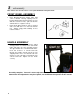
3 unit assembly Note: Please refer to Parts List for correct part identification and placement. FRONT WHEEL ASSEMBLY • • Place Mounting Bracket against lower right corner of Blower Housing, aligning holes in bracket with threaded studs in housing. Secure with three 3/8-16 hex nuts, split lock washers and flat washers. Tighten securely. Install Front Wheel between forks in bracket and secure with 5/8-11 x 5” hex bolt and lock nut. Tighten snugly while allowing for free rotation of wheel.
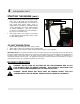
4 unit operation STARTING THE ENGINE IMPORTANT NOTE: The procedures outlined within this section are general guidelines, and are in no way meant to replace or supercede engine manufacturer’s operating instructions. In order to obtain optimum performance from your engine, refer to your engine manual. WARNING! IMPELLER IS MOUNTED DIRECTLY TO ENGINE SHAFT – STARTING ENGINE WILL RESULT IN IMMEDIATE HIGH-VELOCITY DISCHARGE.
4 unit operation (cont.) STARTING THE ENGINE (cont.) • • Bracing unit with one hand on the upper handle and a foot on the right rear tire, firmly grasp recoil handle and pull briskly. You may have to pull several times before engine starts. (If engine fails to start within a reasonable amount of time, discontinue and check engine manual for further instructions.) Note: Do not allow recoil rope to snap back into recoil; damage to the rope or recoil could result.
4 unit operation (cont.) GENERAL RULES TO OBSERVE BEFORE AND DURING OPERATION: • • • • • • • Inspect your unit before each and every use. Check for worn, bent or broken components, loose fasteners, low or flat tires, etc., and repair or replace prior to operation. DO NOT OPERATE A MACHINE THAT IS WORN OR DAMAGED – SERIOUS INJURY OR DEATH CAN RESULT. Clear the entire work area of all debris that could cause damage to or become entangled in the unit.
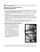
4 unit operation (cont.) HINTS FOR EFFECTIVE OPERATION: • • For operator ease and maneuverability, push down on the upper handle while walking so that the machine balances on the rear wheels. When blowing dry debris, set blower discharge to lower rate; when blowing wet or frozen debris, increase discharge rate. 5 maintenance BEFORE MAKING ANY ADJUSTMENTS, STOP ENGINE AND DISCONNECT SPARK PLUG WIRE TO PREVENT INADVERTENT STARTING OF UNIT.
5 maintenance (cont.) BEFORE MAKING ANY ADJUSTMENTS, STOP ENGINE AND DISCONNECT SPARK PLUG WIRE TO PREVENT INADVERTENT STARTING OF UNIT. TROUBLESHOOTING: • • • UNIT WILL NOT START: • Check fuel and oil levels. • Check to make sure choke is set when engine is cold, off when hot. • Check throttle for proper operation. • Check intake baffle for jammed debris or accumulation of debris. • If condition persists, contact dealer. UNIT STALLS: • Check fuel and oil levels.
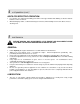
5 maintenance (cont.) ADJUSTMENTS: BEFORE MAKING ANY ADJUSTMENTS, STOP ENGINE AND DISCONNECT SPARK PLUG WIRE TO PREVENT INADVERTENT STARTING OF UNIT. • • THROTTLE CABLE ADJUSTMENT: Correct cable adjustment allows for full range of movement of throttle body on engine in conjunction with throttle control on handle. To adjust, loosen cable clip screw on engine, then slide cable housing in or out in approximately 1/8-1/4” increments. Retighten screw, recheck, and readjust as needed.
6 illustrated parts list ELBX10151BV
6 illustrated parts list (cont’d) Item 1 2 3 Part No.
6 illustrated parts list (cont’d) Item 43 44 45 46 47 48 49 50 51 52 53 54 Part No. 90391 3071800 3031220 90505 90188 76978 91298 --------------------- Qty 4 1 1 1 12 1 8 ----------- Description WASHER, 5/16" Internal Tooth Lock THROTTLE CONTROL, Briggs BUSHING, Flanged .375 x .500 x .25 (.625 x .063 Flange) SCREW, 1/4-20 x 2" Hex Head Cap, GR5 WASHER, .34 x .69 x .
7 decal identification 29776 – EUROPEAN CERTIFICATION – LOCATED ON REAR OF BLOWER HOUSING 75892 – DANGER – FLYING MATERIAL – LOCATED ON SIDE OF BLOWER HOUSING 75893 – EAR/NOSE/BREATHING PROTECTION REQUIRED – LOCATED ON SIDE OF BLOWER HOUSING 22841 – DANGER – KEEP HANDS AND FEET AWAY – LOCATED ABOVE BLOWER DISCHARGE 29490 – MODEL YEAR 2004 – LOCATED ON REAR OF BLOWER HOUSING 78069 – NOISE RATING – LOCATED ON REAR OF BLOWER HOUSING
7 decal identification (cont’d) 73462 – WARNING COMBO – LOCATED ON TOP OF BLOWER HOUSING 75760 – SNAPPER LOGO – LOCATED ON INTAKE BAFFLE (ON APPLICABLE MODELS) 75861 / 29445 – GIANT-VAC LOGO – LOCATED ON MID-HANDLE PANEL (ON APPLICABLE MODELS) 3079269 – ‘EASY-OFF IMPELLER’ – LOCATED ON INTAKE BAFFLE 3079268 – ‘NO FLAT TIRES’ – LOCATED ON INTAKE BAFFLE 1722551 – SIMPLICITY LOGO – LOCATED ON INTAKE BAFFLE AND MID-HANDLE PANEL (ON APPLICABLE MODELS) EUROPEAN PERFORMANCE: Maximum level of vibration measu
NOTES ______________________________________________________________________ ______________________________________________________________________ ______________________________________________________________________ ______________________________________________________________________ ______________________________________________________________________ ______________________________________________________________________ ______________________________________________________________________ _________
NOTES ______________________________________________________________________ ______________________________________________________________________ ______________________________________________________________________ ______________________________________________________________________ ______________________________________________________________________ ______________________________________________________________________ ______________________________________________________________________ _________
NOTES ______________________________________________________________________ ______________________________________________________________________ ______________________________________________________________________ ______________________________________________________________________ ______________________________________________________________________ ______________________________________________________________________ ______________________________________________________________________ _________
European Extreme Series Walk-Behind Leaf Blower Series 1 Manual No. 7078092 (I.R.