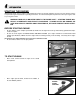
ASSEMBLY INSTRUCTIONS OPERATOR’S MANUAL PARTS LIST European Extreme Series Walk-Behind Leaf Blower Series 2 Actual product may differ slightly from product pictured above Models Covered: ELBX10152BV Manual No. 7043324 (I.R.
1 preliminaries Congratulations! You have just purchased one of the finest pieces of outdoor power equipment on the market today. If properly cared for, your new blower will provide years of dependable service. Please read and follow this instruction manual carefully in order to get the most out of your new equipment.
2 safety rules regarding outdoor power equipment ! IMPORTANT! READ CAREFULLY THE FOLLOWING SAFETY RULES BEFORE ASSEMBLING OR OPERATING UNIT. • Never operate with guards not securely in place. Be sure all safety features are attached, adjusted properly and functioning properly. • Never operate with the discharge deflectors removed or altered. • Do not change the engine governor setting or over speed the engine. • Stop on level ground, shut off engine before leaving the operator’s position for any reason.
2 safety rules regarding outdoor power equipment (cont.) • Shut off fuel while storing or transporting. Do not store fuel near flames or drain indoors. • Keep all hardware, especially impeller bolt, tight and keep all parts in good working condition. Replace all worn or damaged decals. • Never tamper with safety devices. Check their proper operation regularly. • Clean leaves and debris from mufflers and engine to prevent fires. Clean up oil or fuel spillage.
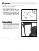
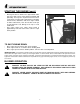
3 unit assembly Note: Please refer to Parts List for correct part identification and placement. FRONT WHEEL ASSEMBLY • • Place Mounting Bracket against lower right corner of Blower Housing, aligning holes in bracket with threaded holes in housing. Secure with three 3/8-16 x 1 hex bolts, split lock washers and flat washers. Tighten securely. Install Front Wheel between forks in bracket, slide sleeve through bracket and wheel, and secure with 1/213 x 5” hex bolt and lock nut.
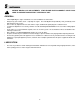
4 unit operation STARTING THE ENGINE IMPORTANT NOTE: The procedures outlined within this section are general guidelines, and are in no way meant to replace or supercede engine manufacturer’s operating instructions. In order to obtain optimum performance from your engine, refer to your engine manual. ! WARNING! IMPELLER IS MOUNTED DIRECTLY TO ENGINE SHAFT – STARTING ENGINE WILL RESULT IN IMMEDIATE HIGH-VELOCITY DISCHARGE.
4 unit operation (cont.) STARTING THE ENGINE (cont.) • • Bracing unit with one hand on the upper handle and a foot on the right rear tire, firmly grasp recoil handle and pull briskly. You may have to pull several times before engine starts. (If engine fails to start within a reasonable amount of time, discontinue and check engine manual for further instructions.) Note: Do not allow recoil rope to snap back into recoil; damage to the rope or recoil could result.
4 unit operation (cont.) GENERAL RULES TO OBSERVE BEFORE AND DURING OPERATION: • • • • • • • Inspect your unit before each and every use. Check for worn, bent or broken components, loose fasteners, low or flat tires, etc., and repair or replace prior to operation. DO NOT OPERATE A MACHINE THAT IS WORN OR DAMAGED – SERIOUS INJURY OR DEATH CAN RESULT. Clear the entire work area of all debris that could cause damage to or become entangled in the unit.
5 ! maintenance BEFORE MAKING ANY ADJUSTMENTS, STOP ENGINE AND DISCONNECT SPARK PLUG WIRE TO PREVENT INADVERTENT STARTING OF UNIT. GENERAL: • • • • • • • • Follow implicitly the engine manufacturer’s recommendations for maintenance. Always keep your machine clean – especially the engine. Check all adjustments periodically. Also, periodically check that all fasteners are secure. Never make any adjustments to the unit until the engine is off and the spark plug wire is disconnected.
5 ! maintenance (cont.) BEFORE MAKING ANY ADJUSTMENTS, STOP ENGINE AND DISCONNECT SPARK PLUG WIRE TO PREVENT INADVERTENT STARTING OF UNIT. TROUBLESHOOTING: • • • UNIT WILL NOT START: • Check fuel and oil levels. • Check to make sure choke is set when engine is cold, off when hot. • Check throttle for proper operation. • Check intake baffle for jammed debris or accumulation of debris. • If condition persists, contact dealer. UNIT STALLS: • Check fuel and oil levels.
5 maintenance (cont.) ADJUSTMENTS: ! • BEFORE MAKING ANY ADJUSTMENTS, STOP ENGINE AND DISCONNECT SPARK PLUG WIRE TO PREVENT INADVERTENT STARTING OF UNIT. THROTTLE CABLE ADJUSTMENT: Correct cable adjustment allows for full range of movement of throttle body on engine in conjunction with throttle control on handle. To adjust, loosen cable clip screw on engine, then slide cable housing in or out in approximately 1/81/4” increments. Retighten screw, recheck, and readjust as needed.
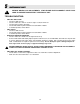
6 illustrated parts list 12
6 illustrated parts list (cont.) Item Part No.
6 illustrated parts list (cont.) Item Part No. Qty Description 43 44 45 46 47 48 49 50 51 52 53 54 54 55 --- 90391 3071800 7078169 90505 90188 76978 91298 91601 75893 29776 7078087 27255 1722551 73462 22841 7011279 4 1 2 1 14 1 4 4 1 1 1 1 1 1 1 1 WASHER, 5/16" Internal Tooth Lock THROTTLE CONTROL, Briggs BEARING, 3/8” Clip SCREW, 1/4-20 x 2" Hex Head Cap, GR5 WASHER, .34 x .69 x .
7 decal identification 75893 - EAR/EYE/BREATHING PROTECTION REQUIRED - LOCATED ON SIDE OF BLOWER HOUSING 29776 - EUROPEAN CERTIFICATION LOCATED ON REAR OF BLOWER HOUSING 75892 - DANGER-FLYING MATERIAL LOCATED ON SIDE OF BLOWER HOUSING 22841 - WARNING-CUT FINGER - LOCATED ABOVE BLOWER DISCHARGE 7011279 - MODEL YEAR 2005 - LOCATED ON REAR OF BLOWER HOUSING 7078069 - NOISE RATING - LOCATED ON REAR OF BLOWER HOUSING 15
7 decal identification (cont.
notes 17
notes 18
notes 19
ASSEMBLY INSTRUCTIONS OPERATOR’S MANUAL PARTS LIST European Extreme Series Walk-Behind Leaf Blower Series 2 McDonough, GA 30253 USA Manual No. 7043324 (I.R.