Safety Instructions & Operator’s Manual for EUROPEAN 21” STEEL DECK WALK MOWERS (TYPE ‘M’) SERIES 18 PROPELLED MODELS EMRP216518B MODEL NUMBER EXPLANATION E M R EUROPEAN MODEL MODEL DESIGNATION RECYCLING MODEL SELF-PROPELLED E – European Model P – Self Propelled Model M – Model Designation R – Recycling Model 21 – 21” Cutting Width 65 – 6.
IMPORTANT SAFETY INSTRUCTIONS WARNING: This powerful cutting machine is capable of amputating hands and feet and can throw objects that can cause injury and damage! Failure to comply with the following SAFETY instructions could result in serious injury or death to the operator or other persons. The owner of the machine must understand these instructions and must allow only persons who understand these instructions to operate machine.
IMPORTANT SAFETY INSTRUCTIONS SAFE HANDLING OF GASOLINE OPERATION (Continued From Previous Page) 3. DO NOT remove fuel cap or add fuel with the engine running. Allow the engine to cool before refueling. 4. DO NOT refuel the machine indoors. 5. DO NOT store the machine or fuel container inside where there is an open flame, spark or pilot light such as on a water heater or other appliances. 6. DO NOT fill fuel containers inside a vehicle or on a truck or trailer bed with a plastic liner.
IMPORTANT SAFETY INSTRUCTIONS MAINTENANCE AND STORAGE (Continued From Previous Page) 11. Have machine serviced by an authorized SNAPPER dealer at least once a year and have the dealer install any new safety devices. 12. Use only genuine SNAPPER replacement parts to assure that original standards are maintained.
TABLE OF CONTENTS IMPORTANT SAFETY INSTRUCTIONS ..............................................2 - 4 TABLE OF CONTENTS.............................................................................5 SECTION 1 - FAMILIARIZATION..............................................................6 SECTION 2 - OPERATING INSTRUCTIONS .......................................7-11 Pre-start Checklist................................................................................................
Section 1 - FAMILIARIZATION WHEEL DRIVE CONTROL BLADE CONTROL GROUND SPEED CONTROL FUEL FILLER CAP ROPE START HANDLE OIL FILL CAP AND DIPSTICK ENGINE PRIMER HANDLE KNOB RECYCLING COVER FRONT HEIGHT ADJUSTMENT LATCHES FIGURE 1.1 1.2 NOMENCLATURE The nomenclature drawing above, Figure 1.1, shows the essential parts of the SNAPPER WALK BEHIND MOWERS. It is recommended that all operators of the mower become thoroughly familiar with the controls, parts and operation of the mower before operating.
Section 2 - OPERATING INSTRUCTIONS 2.1.6. Clean exterior surfaces of cutting deck and engine of any accumulation of spilled fuel, dirt, grass, oil, etc. Keep engine air intake screen and cooling fins clear at all times. 2.1 PRE-START CHECK LIST Make the following checks and perform the service required before each start-up. 2.1.1. Check guards, deflectors, grass bag, adapter and covers to make sure all are in place and securely tightened. 2.1.2.
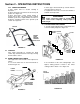
Section 2 - OPERATING INSTRUCTIONS 2.2.2. PROPELLING MOWER 1. Start engine. Refer to Section “Starting & Operation”. 2. Move ground speed control to the desired speed position. See Figure 2.5. 3. Move wheel drive control against handle to engage wheel drive and propel mower forward. Forward speed can be adjusted while the mower is moving by changing position of the ground speed control. See Figure 2.5. 2. Move upper mower handle up or down until the desired position is achieved. 3.
Section 2 - OPERATING INSTRUCTIONS WARNING STEP 2: Install grass catcher by sliding connector over flange of adapter. Attach grass bag hooks over middle handle cross bar. See Figure 2.10. DO NOT attempt any maintenance, adjustments or service with engine and blade running. STOP engine and blade. Disconnect spark plug wire and secure away from spark plug. Engine and components are HOT. Avoid serious burns, allow sufficient time for all components to cool. 2.
Section 2 - OPERATING INSTRUCTIONS 2.8 INSTALLATION, COLLECTOR GRASS BAG (Optional accessory on some models) STEP 1: Install the grass bag adapter and secure to the side and top of the deck with the two nuts provided on the machine. Slot in front edge of adapter must be under nut located on top of deck. See Figure 2.9. STEP 2: Install grass catcher by sliding connector over flange of adapter. See Figure 2.11 WARNING DO NOT operate without entire Grass Catcher or guard in place.
Section 2 - OPERATING INSTRUCTIONS WARNING WARNING DO NOT attempt any maintenance, adjustments or service with engine and blade running. STOP engine and blade. Disconnect spark plug wire and secure away from spark plug. Engine and components are HOT. Avoid serious burns, allow sufficient time for all components to cool. DO NOT operate without entire Grass Catcher or guard in place. Grass Catcher components are subject to deterioration during normal use.
Section 3 – MAINTENANCE 3.2.2. CHECK GREASE LEVEL IN TRANSMISSION 1. Remove transmission fill plug. Roll machine forward or backward while looking down into plug hole. 2. If liquid grease IS NOT visible on the input gear (the small gear below the plug hole), add an amount, to cover gear, of Snapper “00” grease. See Figure 3.2. 3.1 INTRODUCTION To retain the quality of the mower, use genuine SNAPPER replacement parts only. Contact a local SNAPPER dealer for parts and service assistance.
Section 3 – MAINTENANCE 3.2.4. CHECK ENGINE DRIVE BELT 1. Visually check engine drive belt for cracking, fraying, severed or belt strands exposed. If worn or damaged, replace belt before operating mower. 3.2.2. CHECK GREASE LEVEL IN TRANSMISSION (Continued from previous page) NOTE: Do not spill grease or oil on surface of drive disc. See Figure 3.3. 3. Reinstall transmission plug. 4. Check grease level after each 25 hours of operation. 3.2.5. CHECK TRANSMISSION POLY-V BELT 1.
Section 4 - REPAIR & ADJUSTMENTS WARNING WARNING DO NOT attempt any maintenance, adjustments or service with engine and blade running. STOP engine and blade. Disconnect spark plug wire and secure away from spark plug. Engine and components are HOT. Avoid serious burns; allow sufficient time for all components to cool. Wear heavy leather gloves when handling or working around cutting blades. Blades are extremely sharp and can cause severe injury.
Section 4 - REPAIR & ADJUSTMENTS WARNING CLUTCH CABLE DO NOT attempt any maintenance, adjustments or service with engine and blade running. STOP engine and blade. Disconnect spark plug wire and secure away from spark plug. Engine and components are HOT. Avoid serious burns, allow sufficient time for all components to cool. VINYL SPRING COVER 1/16” TO 1/8” CLEARANCE UPPER SPRING CLUTCH CABLE EYE SPRING HOOK LOWER SPRING 4.1.2. BLADE SHARPENING 4.
Section 4 - REPAIR & ADJUSTMENTS USE NEEDLE NOSE PLIERS TO INSTALL DRIVE SPRING WARNING DO NOT attempt any maintenance, adjustments or service with engine and blade running. STOP engine and blade. Disconnect spark plug wire and secure away from spark plug. Engine and components are HOT. Avoid serious burns, allow sufficient time for all components to cool. 4.3 DRIVEN AND DRIVE DISC SERVICE If the mower does not propel itself properly, See Figure 4.6.
Section 4 - REPAIR & ADJUSTMENTS WARNING 1/8” MEASUREMENT TO OUTSIDE EDGE OF DRIVE DISC DO NOT attempt any maintenance, adjustments or service with engine and blade running. STOP engine and blade. Disconnect spark plug wire and secure away from spark plug. Engine and components are HOT. Avoid serious burns, allow sufficient time for all components to cool. DRIVE DISC SLIDE DRIVEN DISC ASSEMBLY TOWARD OUTSIDE EDGE 4.3.3. DRIVEN DISC ADJUSTMENT (Continued From Previous Page) 2.
Section 4 - REPAIR & ADJUSTMENTS 4.3.5. Replacing Bearing In Driven Disc Assembly IMPORTANT: The bearing, on these “M” series machines, is staked into the thrust plate. The bearing will have to be driven out with a mallet and a large punch. A new bearing with four retaining screws will have to be purchased to replace existing bearing. If the driven disc bearing requires replacement, remove the driven disc assembly and replace bearing as follows: 1.
Section 4 - REPAIR & ADJUSTMENTS 4.4.1. Engine Drive Belt Replacement (Stretch Type Belts) 1. Empty the fuel tank. 2. Note the belt routing in Figure 4.15. There is no idler pulley on these models to disconnect. See Figure 4.15. WARNING DO NOT attempt any maintenance, adjustments or service with engine and blade running. STOP engine and blade. Disconnect spark plug wire and secure away from spark plug. Engine and components are HOT. Avoid serious burns, allow sufficient time for all components to cool.
Section 4 - REPAIR & ADJUSTMENTS 9. Loop the belt around the pulley on the bottom of the drive disc. 10. Reinstall drive disc and retaining hardware. IMPORTANT: 1) The square shoulder of the drive disc bolt must fit into the square hole of the bushing. 2) The square end of bushing must fit into the bracket slot. 11. Reinstall belt cover and tighten bolts securely. 12. Reinstall blade hub and cutter blade. Recommended torque for blade cap screw is 40 ft. lbs.
TROUBLESHOOTING PROBLEM Engine Will Not Start Using Recoil Starter PROBABLE CAUSE 1. Fuel tank empty. 2. Engine needs choking or priming. 3. Spark plug wire disconnected. Engine Stalls or Stops 1. Blade control is released or is not being held securely After Running against handle. 2. Fuel tank empty. 3. Engine air pre-cleaner and or air cleaner dirty. 4. Spark plug defective or gap set improperly. 5. Water, debris or stale fuel in fuel system. Engine Loses Power 1.
SERVICE SCHEDULE ITEM SERVICE PERFORMED Engine Oil REF. EACH USE X 5 HRS 25 HRS Check Oil Level Page 7 Initial Oil Change Page 12 Periodic Oil Change Page 13 X* Clean Sponge Element X** 50 HRS 100 HRS X Air Cleaner Clean or Replace Engine Manual & Page 13. Engine Manual. Spark Plug Replace Engine Manual.
DECAL IDENTIFICATION KEEP CHILDREN AND OTHERS OUT OF MOWING SAFETY ALERT SYMBOL. OBSERVE AND FOLLOW ALL SAFETY INSTRUCTIONS. READ, UNDERSTAND AND FOLLOW INSTRUCTIONS AND WARNINGS IN OPERATOR’S MANUALS, AND ON THE MOWER, ENGINE AND ATTACHMENTS BEFORE OPERATING. (1) WARNING INSTRUCTIONS. (5) SPEED SELECTOR: Shows direction of motion and the ability to select one of six ground speeds by rotating the lever. (2) WARNING: Do Not operate without entire Grass Catcher or Guard in place.
DECAL IDENTIFICATION (8) INJURY WARNING: Indicates possible severe injury from rotating cutting blades. (6) OPERATOR PRESENCE CONTROL (OPC): Arrow points to the OPC bail. When bail is rotated rearward, the engine may be started and will run as indicated by the engine with rotating arrow. With the engine running, the blade is rotating as indicated by the cut grass symbol. When the bail is released and rotates forward, the engine will stop. (9) CE DECAL: Indicates European Certification.
2 YEAR LIMITED WARRANTY For two (2) years from purchase date for the original purchaser's residential, non-commercial use, SNAPPER, through any authorized SNAPPER dealer will replace, free of charge (except for taxes where applicable), any part or parts found upon examination by the factory at McDonough, Georgia, to be defective in material or workmanship or both.
NOTES 24 26
NOTES 25 27
Safety Instructions & Operator’s Manual for EUROPEAN 21” STEEL DECK WALK BEHIND MOWERS (TYPE ‘M’) SERIES 18 IMPORTANT Snapper products are built using engines that meet or exceed all applicable emissions requirements on the date manufactured. The labels on those engines contain very important emissions information and critical safety warnings. Read, Understand, and Follow all warnings and instructions in this manual, the engine manual, and on the machine, engine and attachments.