() Simplicilq GIAN'r-VAC'_ OPERATOR'S MANUAL Field and Brush Mower Mfg. No. 7085922 Model No. FB13250BS Description 13 hp Briggs, Hydro-Drive 7085923 GM2515KAW 15 hp Kawasaki, 7085924 GM2513H 13 hp Honda, Hydro-Drive Hydro-Drive Manual No. 7078128 (Rev.
Tableof Contents Identification Numbers ........................................ Safety Rules & Information ................................. Safety Decals ....................................................... Features & Controls ............................................ Control Functions .................................................... 1 2 4 6 6 Operating the Mower ........................................... 7 Starting the Engine .................................................
SafetyRules& Information Read these safety rules and follow them closely. Failure to obey these rules could result in loss of control of unit, severe personal injury or death to you, or bystanders, or damage to property or equipment. This mowinq deck is capable of amputating hands and feet and throwing objects. The triangle in text signifies important cautions or warnings which must be followed.
SafetyRulesandInformation, SLOPE OPERATION SERVICE WARNING • Use extra care when handling gasoline and other fuels. They are flammable and vapors are explosive. Never operate on slopes greater than 17.6 percent (10 °) which is a rise of 3-1/2 feet (106 cm) vertically in 20 feet (607 cm) horizontally. a) Use only an approved container. b) Never remove fuel cap or add fuel with the engine running. Allow engine to cool before refueling. Do not smoke. Select slow ground speed before driving onto slope.
SafetyRules& Information SERVICE AND MAINTENANCE • Use extra care in handling gasoline and other fuels. They are flammable and vapors are explosive. a) Use only an approved container. b) Never remove gas cap or add fuel with the engine running. Allow engine to cool before refueling. Do not smoke. c) Never refuel the unit indoors.
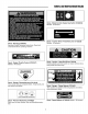
SafetyandinstructionalDecals Decal - Blade Control, Engine Key Switch (7028349) Models - All mowers Decal - Traction Drive / Freewheel Lever (1725229) Models - All mowers Decal - Warning (7028490) Important Safety Operating Instructions. Read and understand before operating machine Decal - Caution - Open Belt Drive (707359) Rotating blades and other parts can cause serious injury. Keep hands and feet away.
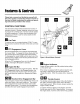
Features& Controls Please take a moment and familiarize yourseff with the name, location, and function of these controls so that you will better understand the safety and operating instructions provided in this manual. CONTROL FUNCTIONS The information below briefly describes the function of individual controls. Starting, stopping, driving, and mowing require the combined use of several controls applied in specific sequences.
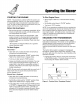
Operatingthe Mower STARTING THE ENGINE To Shut Engine Down: • Allow engine to idle for 2-3 minutes before shutting down. NOTE - The procedures outlined within this section are general guidelines, and are in no way meant to replace or supercede engine manufacturer's operating instructions, In order to obtain optimum performance from your engine, refer to your engine manual Before Starting • Set throttle control down to "SLOW" position. • Turn key to "OFF" position.
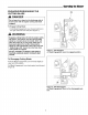
Operating theMower To Propel Unit Forward: IN CASE OF EMERGENCY, SUCH AS IMPORTANT NOTE LOSS OF CONTROL OR POTENTIAL COLLISION, RELEASE TRACTION DRIVE ENGAGEMENT BAR. THIS WILL IMMEDIATELY DISENGAGE THE TRANSMISSION AND STOP MOWER MOVEMENT. THE ENGINE WILL CONTINUE TO RUN. Q • Grasping both upper handle/safety bar (A, Figure 5) and lower portion of traction drive engagement bar (B) with both hands, slowly begin squeezing engagement bar up toward handle. The unit should begin moving forward.
OperatingtheMower ENGAGING/DISENGAGING CUTTING BLADE THE DANGER Do not pass by or stand on the discharge side of brush mower with its engine running and blade engaged. To Engage Cutting Blade: • Push Blade Engagement Lever forward and then to the right until lever locks into place (Figure 7). WARNING Engaging cutting blade will activate engine safety kill feature.
Operating theMower TO ADJUST CUTTING HEIGHT The front skids on the brush cutter have 3 sets of holes (Figure 9) for height adjustment: - Top holes - 3 1/4"cutting depth - Center holes - 4" cutting depth - Bottom holes - 4 3/4"cutting depth • Shut off engine. • Loosen bolts holding skids. • Move skid to desired location. • Reinstall bolts. Figure 9 - Adjusting Height A. Skid B. Capscrew C.
Regular Maintenance LUBRICATION Service Interval: Every 25 Hours Lubricate the unit at the locations shown in Figure 10 as well as the lubrication points listed. Generally, all moving parts should be oiled where contact is made with other parts. Keep oil and grease off belts and pulleys. Wipe surfaces clean before and after lubrication. Grease: • blade arbor Note - This grease point is located under the blade deck, on the arbor.
RegularMaintenance TIRE PRESSURE Tire pressure is 20 psi (1.4 bar). BATTERY SERVICE WARNING Figure 12. Check Tire Pressure When removing or installing battery cables, disconnect the negative cable FIRST and reconnect it LAST. If not done in this order, the positive terminal can be shorted to the frame by a tool. Cleaning the Battery and Cables 9HP Models Service Interval: Every 100 Hours 1. Disconnect the cables from the battery, negative cable first (C, Figure 13a). 2.
RegularMaintenance, SERVICING THE MOWER BLADES WARNING For your personal safety, do not handle the sharp mower blades with bare hands. Careless or improper handling of blades may result in serious injury. Service Interval: Every 100 Hours or As Required 1. Raise the front end of the brush mower and securely support in the raised position. • LOOSEN 2. Blades should be sharp and free of nicks and dents. If worn or damaged, replace the blades as described in following steps. 3.
Troubleshooting, Adjustment, & Service TROUBLESHOOTING PROBLEM CAUSE REMEDY Engine will not turnover or start. 1. PTO lever in the engaged position. 2. Out offuel. Place in disengaged position. If the engine is hot, allow it to cool, then refill the fuel tank. Disengage choke. See Battery Maintenance Section. Turn off fuel and replace filter. Recharge or replace. Visually check wiring & replace broken or frayed wires. Tighten loose connections. See your dealer. See your dealer.
Troubleshooting, Adjustment& Service, Troubleshooting Cont. Blade will not engage. 1. 2. Blade clutch rod too loose. Blade belt worn or broken. 3. Over-stretched or broken spring on blade clutch rod. Worn blade clutch. 4. Blade will not disengage or Blade stop time over 5 seconds. 1. 2. Mower drive belt slips. Mower cut is uneven. Mower cut is rough looking. 1. 2. 3. 4. 1. 2. 1. 2. 3. 4. 5. 6. 7. Excessive mower vibration. 1. 2. 3. 4. 5. Excessive belt wear or breakage. 1. 2.
Troubleshooting, Adjustment, & Service TRAVEL CONTROL Serial Number ADJUSTMENT \ 0-011903999 1. The Travel Control engagement bars (A, Figure 16a) should be an equal distance from the Upper Handle Bar. If they are not, adjust their position. 2. Loosen the wing nut Iocknut (D) and rotate control rod (C) until engagement bars are properly adjusted. 3. Tighten Iocknut to secure adjustment. Figure 16a- Travel Controls Adjustment A. Engagement Bars B. Upper Handle C. Control Rod D.
Troubleshooting, Adjustment, & Service BLADE CLUTCH ADJUSTMENT WARNING Shut off engine before attempting this adjustment procedure. If the mower blade does not stop running when the blade clutch lever is in the DISENGAGED position, does not run at full speed, adjust the Blade Clutch tension. 1. Remove clutch cover plate (A, Figure 19). 2. Loosen nut (D, Figure 17). 3. Remove hairpin clip (E). 4. Slide clutch rod fitting (C) out of blade clutch lever (B). 5.
Troubleshooting, Adjustment, & Service BLADE BRAKE ADJUSTMENT WARNING • DO NOT place hands or feet under mower deck and away from blade. • This machine is capable of throwing objects and debris. Keep bystanders away. • DO NOT touch any rotating parts (pulleys, belts, etc.). Loose clothing, gloves, etc. can become entangled. The mower blade should stop within 5 seconds after the Blade Engagement Lever is moved to the DISENGAGED position. This adjustment is checked by: Figure 18 - Blade Spindle Brake A.
Troubleshooting, Adjustment, & Service TRACTION DRIVE BELT ADJUSTMENT If the mower drive is not functioning properly, the drive belt may need to be adjusted; For SIN 0 - 071601075 The traction drive belt tension is adjusted by a bolt and screw system. To adjust belt tension: 1. Loosen traction drive idler pulley lock nut (D, Figure 19). 2. Loosen or tighten traction drive idler pulley adjustment nut (E, Figure 19) as required.
Troubleshooting, Adjustment & Service MOWER BELT REPLACEMENT To replace the mower blade drive belt; NOTE - The traction drive belt will have to be removed before the mower blade belt can be removed. 1. Remove clutch cover plate (A, Figure 23). 2. On early models only, loosen traction drive belt idler pulley lock nut (D, Figure 23) for the traction drive. 3. Loosen idler pulley adjustment by rotating adjustment nut (late models, A, Figure 22) or (early models, E, Figure 23). 4.
Specifications NOTE: Specifications are correct at time of printing and are subject to change without notice. * Actual sustained equipment horsepower will likely be lower due to operating limitations and environmental factors. ENGINEI BRIGGS HONDA KAWASAKI BRIGGS 13 HP B&S 13 HP Honda 15 HP V-twin 16 HP B&S Transmission Hydro!Variable Hydro/Variable Hydro/Variable Hydro/Variable Ground Speed (mph) Infinite (.01 - 6) Infinite (.01 - 6) Infinite (.01 - 6) Infinite (.
Notes 22
Notes 23
A Division of Simplicity Manufacturing, 535 Macon Street/PO Box 777 McDonough, GA 30253 © Copyright 2005 All Rights Reserved. Printed in USA. Inc.