Safety Instructions & Operator's Manual for TWO STAGE INTERMEDIATE FRAME SNOW THROWER SERIES 4 MODELS 155224 MODEL NUMBER EXPLANATION I I Iss122141 MODEL DESIGNATION ENGINE HP I - Intermediate Frame Model I 17244 I SERIES DESIGNATION AUGER WIDTH 55 - 5.5 Engine HP (Engine Horse Power) 7 - 7.
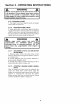
IMPORTANT SAFETY INSTRUCTIONS WARNING: This powerful machine is capable of amputating hands and feet and can throw objects that can cause injury and damage! Failure to comply with the following instructions may result in serious injury to the operator or other persons. The owner of the snow thrower must understand these instructions and, furthermore, must allow only persons who understand these instructions to operate snow thrower.
IMPORTANT OPERATIONAL SAFETY PRECAUTIONS (Continued From Previous Page) 7. DO NOT put hands or feet near or under rotating parts. Keep clear of the discharge opening at all times. 8. Start engine only where exhaust fumes will be safely dissipated. Allow a brief warm-up period, and practice operation of controls outside before putting the machine to work. 9. After striking a foreign object, STOP the engine (motor), remove the key, and remove the wire from spark plug.
TABLE SECTION 1 - IMPORTANT TABLE OF CONTENTS SECTION OF CONTENTS SAFETY INSTRUCTIONS .......................... 2-3 ............................................................................ 2 - OPERATING INSTRUCTIONS ......................................... 4 5-9 Pre-start Checklist ..................................................................................................... Starting & Stopping Recoil Start Engine ...............................................................
Section 2 - OPERATING 2.1 INSTRUCTIONS PRE-START CHECK LIST Make the following checks and perform the service required before each start-up. 2.1.1. Check engine oil and add oil as needed to bring level up to the FULL mark. Refer to engine owner's manual for oil specifications. 2.1.2. Check guards, chutes, deflectors and covers to make sure all are in place and securely tightened. 2.1.3. Check auger control and wheel drive control to insure cables are connected and both levers operate freely. See Figure 2.
Section 2 - OPERATING 2.2 INSTRUCTIONS STARTING, OPERATION & STOPPING (RECOIL START MODELS) 2.2.1. ENGINE 1. Turn fuel shut off valve to the "ON" position. See Figure 2.3. 5. Push primer button three times to start a cold engine. NOTE: Do not use primer button to start warm engine. See Figure 2.4. 6. Pull rope start handle to crank engine. 7. After engine starts, move the choke control to the no choke "OFF" position. Allow a brief warm-up until engine runs smooth. 2.2.2.
Section 2 - OPERATING INSTRUCTIONS 2.2.5. Objects can be thrown by the snow thrower while it is in operation. Thrown objects could cause serious injury to the operator or bystanders. Always wear safety goggles or other suitable eye protection. Keep people and pets away from area. 2.2.3. ENGAGING AUGER 1. Move auger control lever against engage auger. See Figure 2.6. handle to 2.2.4. ENGAGING WHEEL DRIVE 1. Move wheel drive control lever against handle to engage wheel drive. See Figure 2.6.
Section 2 - OPERATING 2.2 INSTRUCTIONS STARTING, OPERATION & STOPPING (ELECTRIC START MODELS) PUSH STARTER BUTTON DO NOT use an electrical extension cord that is damaged. A damaged electrical extension cord could cause a shock or fire. Thoroughly inspect electrical extension cord before using machine. If cord is damaged, do not use and do not operate machine. Replace damaged cord immediately. Contact your Snapper service dealer for assistance.
Section 2 - OPERATING INSTRUCTIONS WARNING Objects can be thrown by the snow thrower while it is in operation. Thrown objects could cause serious injury to the operator or bystanders. Always wear safety goggles or other suitable eye protection. Keep people and pets away from area. 2.2.9. ENGAGING AUGER 1. Pull auger control lever against handle to engage auger. Refer to Figure 2.6. 2.2.10. ENGAGING WHEEL DRIVE 1. Move wheel drive control lever against handle to engage wheel drive.
Section 3 - MAINTENANCE 3.3 DO NOT attempt any adjustments, maintenance, service, or repairs, with engine running. Stop auger. Stop engine. Remove key. Disconnect spark plug wire and secure wire away from spark plug. 3.1 INTRODUCTION To retain the quality of the snow thrower, use only genuine SNAPPER replacement parts. Contact a local SNAPPER dealer for parts and service assistance. For the correct part or information for a particular snow thrower, always mention model and serial number. 3.
Section 3 - MAINTENANCE 3.4 ANNUALLY (END OF EACH SEASON) Perform all maintenance as described in the maintenance schedule. 3.4.1. Engine Refer to engine instructions. 3.4.2. Spark Plug Refer to engine instructions. owner's manual for service owner's manual for service 3.5 STORAGE PROCEDURE Refer to the Engine Owner's Manual for directions regarding engine storage preparations. Prepare the snow thrower for "end of season" storage as follows: 1.
Section 4 - REPAIR & ADJUSTMENTS 4.1.2. AUGER BELT IDLER PULLEY ADJUSTMENT NOTE: To adjust the idler pulley and properly tension the auger belt, the auger control cable adjustment must first be loosened as described in the following step. Cable adjustment must be checked after completing the idler pulley adjustment. 1. Loosen jam nut at the end of cable. Hold threaded end of cable and then turn metal housing of cable counter clockwise until threaded portion of cable is extracted from metal housing.
Section 4 - REPAIR & ADJUSTMENTS 5. Tilt machine forward to gain access to drive system area. Secure machine in the tilted position to prevent tipping over. Remove drive system cover plate. See Figure 4.5. WARNING DO NOT attempt any adjustments, maintenance, service, or repairs, with engine running. Stop auger. Stop engine. Remove key. Disconnect spark plug wire and secure wire away from spark plug. Before tilting machine, drain all the fuel from fuel tank.
Section 4 - REPAIR & ADJUSTMENTS 5. Tilt machine forward to gain access to drive system area. Secure machine in the tilted position to prevent tipping over. Remove drive system cover plate. See Figure 4.7. WARNING DO NOT attempt any adjustments, maintenance, service, or repairs, with engine running. Stop auger. Stop engine. Remove key. Disconnect spark plug wire and secure wire away from spark plug. Before tilting machine, drain all the fuel from fuel tank.
Section 4 - REPAIR & ADJUSTMENTS 4.1.5. GROUND SPEED ADJUSTMENT NOTE: It is recommended to remove the drive system cover and check rubber drive tire engagement with drive disc when adjusting ground speed. 1. Tilt machine forward to gain access to drive system area. Secure machine in the tilted position to prevent tipping over. Remove drive system cover plate. Refer to Figure 4.7. 2. Loosen the top screw that connects the shift rod to the shift hub. See Figure 4.8. 3.
Section 4 - REPAIR & ADJUSTMENTS 4.1.8. SINGLE HANDLE CONTROL ADJUSTMENT (7 HP Models Only) IMPORTANT: Standing in the operator's position, the left handle bar lever is for wheel drive engagement and disengagement. The right handle bar lever is for auger/impeller engagement and disengagement. Hold both levers down to handle bar for engagement and release levers for disengagement.
Section 4 - REPAIR & ADJUSTMENTS 4.1.10. WARNING DO NOT attempt any adjustments, maintenance, service, or repairs, with engine running. Stop auger. Stop engine. Remove key. Disconnect spark plug wire and secure wire away from spark plug. Before tilting machine, drain all the fuel from fuel tank. Allow engine to run, outdoors where fumes can be safely dissipated, until all fuel is removed from carburetor. RUBBER DRIVE TIRE REPLACEMENT 1. Tilt machine forward to gain access to drive system area.
TROUBLESHOOTING PROBLEM PROBABLE CAUSE CORRECTIVE ACTION 1. Fill fuel tank with fresh fuel/oil mix. Engine Will Not Start 1. Fuel tank empty• Using Recoil Starter 2. Engine needs choking and priming• Spark plug wire disconnected• 4. Fuel shut off valve closed• 2. Move Push 3. Place 4. Move Engine Will Not Start Using Electric Starter 1 • Power extension cord not plugged into machine or 120 Volt outlet for U.S.A. or 230 Volt for Europe• 2. Power extension cord damaged• 3.
2 YEAR LIMITED WARRANTY For two (2) years from purchase date for the original purchaser's residential, non-commercial use, SNAPPER, through any authorized SNAPPER dealer will replace, free of charge (except for taxes where applicable), any part or parts found upon examination by the factory at McDonough, Georgia, to be defective in material or workmanship or both.
SNAPPER PRODUCT REGISTRATION IMPORTANT: KEEP THIS INFORMATION (Complete Model the following FORM FOR YOUR PERSONAL information on your Snapper RECORDS purchase) Number Serial Number Date of Purchase Retailer Retailer's Phone Number It is very warranty Snapper important coverage. Please at P.O. Box 1379, Or you may register You can contact Service that register your mail your product McDonough, purchase registration Georgia Snapper to ensure card to: 30253.
Safety Instructions & Operator's Manual for ® TWO STAGE INTERMEDIATE FRAME SNOW THROWER SERIES 4 IMPORTANT Snapper products are built using engines that meet or exceed all applicable emissions requirements on the date manufactured. The labels on those engines contain very important emissions information and critical safety warnings. Read, Understand, and Follow all warnings and instructions in this manual, the engine manual, and on the machine, engine and attachments.