OPERATOR’S MANUAL Large Frame Snowthrowers 1226 Models 1632 Models Mfg. No. 1695324 1695325 1695326 1695327 Mfg. No. 1695336 1695337 1695338 Description L1226E, Snowthrower L1226EX, Snowthrower (CE) L1226E, Snowthrower L1226EX, Snowthrower (CE) Description 1632E, Snowthrower 1632EX, Snowthrower (CE) L1632E, Snowthrower 1428 Models Mfg. No. 1695328 1695329 1695330 1695331 Description L1428E, Snowthrower L1428EX Snowthrower (CE) L1428E, Snowthrower L1428EX Snowthrower (CE) 1530 Models Mfg. No.
Table of Contents CONTENTS: Regular Maintenance Schedule........................................................21 Checking Tire Pressure .................................21 Auger Gear Case Lubrication ........................21 Lubrication .....................................................22 Check / Lubricate Free-Hand Linkage ...........23 Lubricate Auger Shaft Assembly ...................23 Safety Rules & Information General............................................................2 Training .....
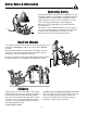
Safety Rules & Information Operating Safety Congratulations on purchasing a superior-quality piece of lawn and garden equipment. Our products are designed and manufactured to meet or exceed all industry standards for safety. Power equipment is only as safe as the operator. If it is misused, or not properly maintained, it can be dangerous! Remember, you are responsible for your safety and that of those around you. Use common sense, and think through what you are doing.
Safety Rules & Information Moving Parts This equipment has many moving parts that can injure you or someone else. However, if you are standing in the operator’s position, and follow all the rules in this book, the unit is safe to operate. The auger and impeller have spinning parts that can amputate hands and feet. Do not allow anyone near the equipment while it is running! DO NOT clear the discharge chute by hand.
Safety Rules & Information This machine is capable to amputating hands and feet and throwing objects. Read these safety rules and follow them closely. Failure to obey these rules could result in loss of control of unit, severe personal injury or death to you, or bystanders, or damage to property or equipment. The triangle in text signifies important cautions or warnings which must be followed. TRAINING OPERATION 1.
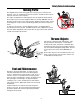
Safety Rules & Information 21. Keep in mind the operator is responsible for accidents occurring to other people or property. 22. Data indicates that operators, age 60 years and above, are involved in a large percentage of power equipment-related injuries. These operators should evaluate their ability to operate the unit safely enough to protect themselves and others from injury. 23. DO NOT wear long scarves or loose clothing that could become entangled in moving parts. 24. Snow can hide obstacles.
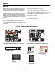
Decals DECALS This unit has been designed and manufactured to provide you with the safety and reliability you would expect from an industry leader in outdoor power equipment. The safety decals below are on your unit.
Decals ALL MODEL DECALS Part No. 1733443 Chute Release Part No. 1733772 Shift Decal CE MODEL DECALS Part No. 1733060 - DANGER / WARNING Main Dash Decal, CE, w/ Easy Turn Part No. 1733059 - DANGER / WARNING Main Dash Decal, CE, w/o Easy Turn Part No. 1727208 Auger Danger Decal Part No.
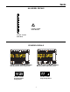
Safety Icons SAFETY ICONS WARNING: READ OPERATOR’S MANUAL. WARNING: DISMEMBERMENT. Read and understand the Operator’s Manual before using this machine. This machine can amputate limbs. Keep bystanders and children away when engine is running. DANGER: THROWN OBJECTS. DANGER: DISMEMBERMENT. This machine is capable of throwing objects and debris. Keep bystanders away. The auger can amputate limbs. Keep hands and feet away from auger and rotating parts. WARNING: REMOVE KEY BEFORE SERVICING.
Identification Numbers SA M North American / CE Models PL E Part No. xxxxxxx SA M xxxxxxxxxxxxxxx Serial No. xxxxxxxxxx xxx PL 20xx E xxxxxxxxxxxxxxxxxxxxxxx xxxxxxxxxxxxxxxxxxxxxxx xxxxxxxxxxxxxxxxxxxxxxx xxxxxxxxxxxxxxxxxxxxxxx CE Models (Only) dB kg: xxx kW: x.
Features, Controls, & Operation CONTROL LOCATIONS IMPORTANT NOTE Please take a moment and familiarize yourself with the name, location, and function of these controls so that you will better understand the safety and operating instructions provided in this manual. The information below briefly describes the function of individual controls. Starting, stopping, and driving require the combined use of several controls applied in specific sequences.
Features & Controls Speed Selector Starter Selects forward speeds 1-6 and reverse speeds 1-2. No neutral position or gate is required, since the traction drive design automatically provides "neutral" (no forward or reverse movement), whenever the Drive Control is released. Electric Start: Depressing the starter button activates the electric starter. The electric start button operates on 120 Volts AC, which is provided by connection to the extension cord provided.
Operation GENERAL OPERATION WARNING This unit is a “two-stage” snowthrower. CHECKS BEFORE EACH START-UP The first stage is the auger, which feeds the snow back into the impeller housing. The second stage is the impeller, which throws the snow out the discharge chute. If bodily contact is made with the auger or impeller when they are rotating, severe personal injury will occur. 1. Make sure all safety guards are in place and all nuts, bolts and clips are secure. 2.
Operation STARTING CONTROLS G See Figure 1 for the following instructions. D Electric Start A. Electric Start Button - The Electric Start Button (A) activates an electric starter mounted to the engine, eliminating the need to pull the starter handle. The Electric Start Button operates on 120 Volts AC, which is provided by connection to the extension cord provided with units equipped with this feature. Connect this extension cord ONLY to a properly grounded 3 prong electrical outlet.
Operation STARTING THE ENGINE CAUTION WARNING This engine was shipped from Briggs & Stratton without oil. Before you start the engine, make sure you add oil according to the instructions in the Engine Owner’s Manual. If you start the engine without oil, it will be damaged beyond repair and will not be covered under warranty. Rapid retraction of starter cord (kickback) will pull hand and arm toward engine faster than you can let go. Broken bones, fractures, bruises or sprains could result.
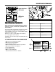
Operation NOTE: If the engine does not start after three attempts, see the “Troubleshooting” section in the Engine Owner’s Manual. D E 11. Allow the engine to warm up for several minutes. Then, slowly move the choke control knob to the run position. B A C C A B F Figure 3. Engine Start/Stop A. Throttle Control Lever B. Fuel Shut-Off Valve C. Safety Key D. Choke Control Knob E. Primer Button F. Starter Cord Handle Figure 4. Engine Start - Electric A. Power Cord Receptacle B. Push Button C.
Operation OPERATING THE SNOWTHROWER WARNING 1. Rotate the discharge chute to the desired direction. When BOTH levers are depressed, the FreeHand™ Control is activated. This allows Auger Engage Control to be released — YET AUGER ROTATION WILL CONTINUE — until the FreeHand™ Control is released. 2. Set the speed selector to the desired forward speed. 3. Fully press and hold the auger engage control (C, Figure 5) on the right-hand grip to begin auger rotation.
Operation GROUND SPEED SELECTOR Use the speed selector (A, Figure 5) to control the drive speed of the snowthrower. There are six forward speeds and two reverse speeds. Use the lower speeds to blow deep or wet snow. Use the higher speeds to blow light snow or to drive the snowthrower without blowing snow. To change speeds, release the auger control lever (B, Figure 5), then move the speed selector to the desired setting. Fully depress the control levers to resume.
Operation FULL TRACTION EASY TURN™ TRACTION Easy Turn™ Lever Released Easy Turn™ Lever Engaged Left Wheel Freewheels, Right Wheel Drives Both Wheels Drive Figure 8. Easy Turn Control A EASY TURN™ FREEWHEELING AND TRACTION DRIVE LOCK B While Clearing Snow: For easy turning when using the snowthrower, squeeze the Easy Turn™ lever (Figure 8). Engaging the Easy Turn™ lever releases the left traction wheel but allows the right wheel to continue driving (Figure 8).
Operation AFTER EACH USE WARNING Normal use of the snowthrower may result in a build-up of packed snow in and around the starter cord housing and around engine controls. Heat from the engine will usually prevent the snow from freezing solid while the unit is running, but after the engine is shut down, some snow may continue melting from engine heat, and later freeze around some moving parts as the unit cools.
20
Regular Maintenance MAINTENANCE SCHEDULE Maintenance Required Frequency Notes Check / Lubricate Free-Hand Linkage. 10 Hours 10W Oil Lubricate snowthrower. 10 Hours 10W Oil and Grease Check tire pressure. Monthly 20 psi (1,38 bar) Change engine oil.*+ 50 Hours See Engine Manual Yearly See Engine Manual 4-6 Hours See Page 28 Yearly Lithium Grease Check auger gear case lubrication.** 25 Hours Benalene Grease Lubricate Auger Shaft.
Regular Maintenance LUBRICATION IMPORTANT NOTE It is very important that grease fittings on the auger shaft are lubricated regularly. If auger rusts to shaft, damage to worm gear may occur if shear pins do not break. A To prevent wheels rusting to axles, it is also necessary to remove the wheels and grease the axles regularly. Remove wheels and grease axles once each year. Apply 5W-30 synthetic motor oil to the friction disk drive hex shaft (A, Figure 13). Figure 13. Drive Lubrication A.
Regular Maintenance CHECK / LUBRICATE FREE-HAND LINKAGE Check the function of the Free-Hand controls. The controls should function as described in the CONTROLS section. It is critical for the safe operation of the unit that the controls disengage when released. Lubricate as shown in Figure 16. IMPORTANT NOTE If the controls do not function properly, lubricate them. If lubrication does not rectify the problem, see your dealer.
Troubleshooting, Adjustments, & Service TROUBLESHOOTING WARNING This section provides troubleshooting and service instructions. Locate the problem and check the possible cause/remedy in the order listed. Before performing any adjustment or service to snowthrower, stop the engine and wait for moving parts to stop. Remove the key. To prevent accidental starting, disconnect the spark plug wire and fasten away from the plug. Also, refer to the Engine Owner’s Manual for additional information.
Troubleshooting Problem Auger rotates, but snow is notthrown far enough. Possible Cause Remedy Chute deflector too low. Adjust deflector as necessary. Engine speed too slow. Set speed to full throttle. Ground speed too fast. Use slower speed selector setting. Snowthrower discharge chute clogged. STOP engine and REMOVE the key. DISCONNECT the spark plug wire. Clear auger using clean-out tool. See warning in SAFETY RULES. Auger belt loose or worn. Check auger drive belt adjustment Poor traction.
Adjustments AUGER DRIVE ADJUSTMENT C WARNING B Do not over-tighten, as this may lift the lever and cause auger drive to be engaged without depressing the Auger Control. A 1. Check that the auger cable (A, Figure 18) is on top of cable button (B) as show in Figure 18. 2. With the drive lever released, the hook (B, Figure 19) should barely touch the lever (C) without raising it. There can be a maximum 1/32” clearance as shown. Figure 18. Auger Cable Button A. Auger Drive Cable B. Auger Cable Button C.
Adjustments A A B B B C D 4-5/16” (10.95cm) C Figure 20. Traction Drive Cable Adjustment A. Cable Boot B. Traction Drive Cable C. “Z” Hook D. Cable Adjustment Bracket Figure 21. Friction Disc Measurement A. Friction Disc B. Frame A 4. Slide the cable boot (A) over the cable adjustment bracket. Run-In Adjustment E B ALL MODELS C 1. After 5 hours of use, check for proper adjustment. Readjust clutch cable if necessary by increasing tension on cable.
Adjustments EASY TURN™ CABLE ADJUSTMENT If the Easy Turn™ cable has stretched, the gears will not disengage when the control lever is activated. Adjust the cable using the following procedure. 1. Turn the engine off and disconnect the spark plug wire. 2. Loosen the jam nut (B, Figure 23). B 3. Turn the adjustment nut (A) to lengthen or shorten the cable.
Adjustments & Service SHEAR PIN REPLACEMENT WARNING B Do not go near the discharge chute or auger when the engine is running. Do not run the engine with any cover or guard removed. A Under most circumstances, if the auger strikes an object which could cause damage to the unit, the shear pin will break. (This protects the gear box and other parts from damage.) A B The shear pins are located on the auger shaft as shown in Figure 26.
Service BELT REPLACEMENT Auger Drive Belt The drive belts are of special construction and must be replaced with original factory replacement belts available from your nearest authorized service center. Some steps require the assistance of a second person. If the auger drive belt is damaged, the snow thrower will not discharge snow. Replace the damaged belt as follows. A A C B 1. Disconnect the spark plug wire. 2. Loosen the capscrews (A, Figure 28) on each side of the bottom panel (B). Figure 28.
Adjustments & Service A A D B B A A C B B D Figure 31. Install Spout Rotator Rod A. Hex Dash Opening B. Spout Rotator Rod Figure 30. Spout Rotator Rod A. Special Nut B. Cover C. Hair Pin D. Spout Rotator Rod 15. Index or point the spout rotator to the center of the machine so the rotator control is in the center of the dash panel. 16. Slide spout rotator rod (B, Figure 31) into hex dash opening (A). A 17. Insert hair pin (C, Figure 30) into spout rotator rod (D). 18.
Service Traction Drive Belt If the snow thrower will not move forward, check the traction drive belt for wear or damage. If the traction drive belt is worn or damaged, replace the belt as follows. 1. Disconnect the spark plug wire. 2. Remove the auger drive belt. See “How To Remove The Auger Drive Belt” in the Service section. 3. Remove the e-ring (J, Figure 29) from one end of the swing plate axle rod (I). 4. Remove the swing plate axle rod (I) to allow the swing plate (A, Figure 33) to pivot forward. 5.
Specifications NOTE: Specifications are correct at time of printing and are subject to change without notice. * The gross power rating for individual gas engine models is labeled in accordance with SAE (Society of Automotive Engineers) code J1940 (Small Engine Power & Torque Rating Procedure), and rating performance has been obtained and corrected in accordance with SAE J1995 (Revision 2002-05). Torque values are derived at 3060 RPM; horsepower values are derived at 3600 RPM.
Parts & Accessories REPLACEMENT PARTS TECHNICAL MANUALS Replacement parts are available from your authorized dealer. Always use genuine Simplicity / Snapper Service Parts. Additional copies of this manual are available, as well as fully illustrated parts lists. These manuals show all of the product’s components in exploded views (3D illustrations which show the relationship of parts and how they go together) as well as part numbers and quantities used.
MANUFACTURING, INC. 500 N Spring Street / PO Box 997 Port Washington, WI 53074-0997 www.SimplicityMfg.com PRODUCTS 535 Macon Street McDonough, GA 30253 www.Snapper.com © Copyright 2007, BRIGGS & STRATTON. All Rights Reserved. Printed in USA.