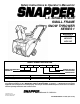
Safety Instructions & Operator’s Manual for L.E. SINGLE STAGE SMALL FRAME SNOW THROWER SERIES 1 MODELS LE3171R LE3191R LE3191E MODEL NUMBER EXPLANATION L E 3 19 MODEL DESIGNATION ENGINE HP L – Light Weight Frame E – Easy Operation 3 – 3.
IMPORTANT SAFETY INSTRUCTIONS WARNING: This powerful machine is capable of amputating hands and feet and can throw objects that can cause injury and damage! Failure to comply with the following instructions may result in serious injury to the operator or other persons. The owner of the snow thrower must understand these instructions and, furthermore, must allow only persons who understand these instructions to operate snow thrower.
IMPORTANT SAFETY INSTRUCTIONS OPERATIONAL PRECAUTIONS CLEARING A CLOGGED DISCHARGE CHUTE 7. Hand contact with the rotating auger/impeller inside the discharge chute is the most common cause of injury associated with snow throwers. DO NOT use your hand to clean out the discharge chute. To clear the chute: 1. STOP the engine. Remove the key. 2. Wait 10 seconds to be sure the auger/impeller blades have stopped rotating. 3. Always use the clean-out tool. DO NOT use your hands. 8. 9. 10. 11. 12. 13. 14.
IMPORTANT SAFETY INSTRUCTIONS 6. Service engine and make adjustments only when engine is stopped. Remove key, remove wire from spark plug, secure wire away from plug, and disconnect cord from electric starting motors to prevent accidental starting. 7. DO NOT change engine governor speed settings or overspeed engine. 8. DO NOT test for spark by grounding the spark plug next to spark plug hole. Spark from the plug could ignite gas exiting engine. 9.
TABLE OF CONTENTS SECTION 1 - IMPORTANT SAFETY INSTRUCTIONS ..........................2-4 TABLE OF CONTENTS.............................................................................5 SECTION 2 - OPERATING INSTRUCTIONS .......................................6-10 Pre-start Checklist ........................................................................................... 6-7 Starting & Stopping Engine (Recoil Start Models)........................................
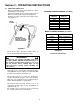
Section 2 - OPERATING INSTRUCTIONS 2.1 PRE-START CHECK LIST Make the following checks and perform the service required before each start-up. 2.1.1. Check guards, chutes, deflectors and covers to make sure all are in place and securely tightened. 2.1.2. Check auger control to insure it works freely. See Figure 2.1. STANDARD FLUID MEASUREMENT (50:1 Ratio) GASOLINE (Gallons) 0.25 0.50 0.75 1.00 1.25 1.50 2.00 AUGER CONTROL 2 CYCLE OIL (Ounces) .64 1.3 1.9 2.6 3.2 3.8 5.
Section 2 - OPERATING INSTRUCTIONS 2.1 PRE-START CHECK LIST (Continued from Previous Page) Make the following checks and perform the service required before each start-up. DANGER DO NOT clean out discharge chute with hands. Contact with moving parts inside chute will cause serious injury. Use clean out tool provided with machine. WARNING DO NOT use an electrical extension cord that is damaged. A damaged electrical extension cord could cause a shock or fire.
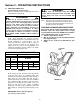
Section 2 - OPERATING INSTRUCTIONS 2.2 STARTING, STOPPING & OPERATION (RECOIL START MODELS) WARNING Release auger clutch control and make sure auger/impeller has STOPPED before rotating discharge chute or adjusting deflector. DO NOT place hands near auger/impeller while engine is running. 2.2.1. ENGINE & AUGER 1. Move choke control to the choke “ON” position. See Figure 2.5. NOTE: Stop the auger by releasing the auger control. Stop the engine by turning the key switch to the “OFF” position.
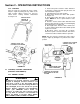
Section 2 - OPERATING INSTRUCTIONS 2.2.4. STOPPING Stop the auger by releasing the auger control. Stop the engine by turning the key switch to the “OFF” position. Always remove key from key switch before leaving machine unattended. See Figure 2.8. 1. Connect the power cord to the starter switch box on machine’s control panel then plug the other end into 120 volt AC receptacle. 2. Turn ignition key to the “ON” position. 3. Move choke control to the choke “ON” position. See Figure 2.9. 4.
Section 2 - OPERATING INSTRUCTIONS WARNING DANGER Objects can be thrown by the snow thrower while it is in operation. Thrown objects could cause serious injury to the operator or bystanders. Always wear safety goggles or other suitable eye protection. Keep people and pets away from area. DO NOT clean out discharge chute with hands. Contact with moving parts inside chute will cause serious injury. Use clean out tool provided with machine. 2.2.6. ENGAGING AUGER 1.
Section 3 - MAINTENANCE 3.1 INTRODUCTION To retain the quality of the snow thrower, use genuine SNAPPER replacement parts only. Contact a local SNAPPER dealer for parts and service assistance. For the correct part or information for a particular snow thrower, always mention model and serial number. 3.2.3 CHECK AUGER CLUTCH CONTROL CABLE 1. Visually check cable for fraying, kinking or severed cable strands. Replace cable and adjust tension before operating snow thrower. See Figure 3.3. 3.
Section 4 - REPAIR & ADJUSTMENTS 4.1.2. AUGER BELT IDLER PULLEY ADJUSTMENT NOTE: To adjust the idler pulley and properly tension the auger belt, the auger control cable adjustment must first be loosened as described in the following step. Cable adjustment must be checked after completing the idler pulley adjustment. WARNING DO NOT attempt any adjustments, maintenance, service, or repairs with engine running. Stop auger. Stop engine. Remove key. Remove spark plug wire and secure wire away from spark plug.
Section 4 - REPAIR & ADJUSTMENTS 4. Push the spring tensioned idler pulley down and install new belt. See Figure 4.5. WARNING DO NOT attempt any adjustments, maintenance, service, or repairs with engine running. Stop auger. Stop engine. Remove key. Remove spark plug wire and secure wire away from spark plug. BELT COVER RETAINING STUDS SHOWN REMOVED 4.1.2. AUGER BELT IDLER PULLEY ADJUSTMENT (Continued From Previous Page) 3. Loosen nut and bolt that secures the idler pulley to idler arm.
Section 4 - REPAIR & ADJUSTMENTS WARNING AUGER DO NOT attempt any adjustments, maintenance, service, or repairs with engine running. Stop auger. Stop engine. Remove key. Remove spark plug wire and secure wire away from spark plug. FLITE SHOE 4.1.3. AUGER BELT REPLACEMENT (Continued From Previous Page) 5. Reinstall belt guide. IMPORTANT: Make sure when reinstalling belt guide that it does not touch drive pulley. Belt guide should an equal amount of clearance on both belt guide fingers. See Figure 4.6. 6.
TROUBLESHOOTING PROBLEM PROBABLE CAUSE Engine Will Not Start Using Recoil Starter CORRECTIVE ACTION 1. Fuel tank empty. 2. Engine needs choking & priming. 3. Spark plug fouled or wire disconnected. Engine Will Not Crank 1. Power extension cord not plugged into machine or Using Electric Starter 110 Volt outlet. 2. Power extension cord damaged. 3. Starter switch damaged or faulty. 4. Key switch turned to “OFF” position. Engine Stalls or Stops 1. Fuel and 2-Cycle oil mixture ratio incorrect.
2 YEAR LIMITED WARRANTY For two (2) years from purchase date for the original purchaser's residential, non-commercial use, SNAPPER, through any authorized SNAPPER dealer will replace, free of charge (except for taxes where applicable), any part or parts found upon examination by the factory at McDonough, Georgia, to be defective in material or workmanship or both.
SNAPPER PRODUCT REGISTRATION FORM IMPORTANT: KEEP THIS INFORMATION FOR YOUR PERSONAL RECORDS (Complete the following information on your Snapper purchase) Model Number__________________________________________________________ Serial Number __________________________________________________________ Date of Purchase ________________________________________________________ Retailer_________________________________________________________________ Retailer’s Phone Number ________________________________________
Safety Instructions & Operator’s Manual for L.E. SINGLE STAGE SMALL FRAME SNOW THROWER SERIES 1 IMPORTANT Snapper products are built using engines that meet or exceed all applicable emissions requirements on the date manufactured. The labels on those engines contain very important emissions information and critical safety warnings. Read, Understand, and Follow all warnings and instructions in this manual, the engine manual, and on the machine, engine and attachments.