51-3845, 7/04 1 M26 SERIES Mechanical Windrow Sweeper For Simplicity Legacy SWEEPSTER, Inc. 2800 N.
51-3845, 7/04
51-3845, 7/04 3 Table of Contents Section 1 ... Operation and Maintenance Section 2 ... Service Section 3 ... Parts Section 4 ...
51-3845, 7/04
1-3845, 7/04 5 Operation and Maintenance M26 Series Table of Contents Introduction .............................................................. 7 Safety .................................................................... 6-12 General Safety Information ..................................... 8-9 Safety Signs and Labels .................................... 10-12 Operation ............................................................ 13-20 Installation ......................................................
SAFETY SECTION Introduction 51-3845, 7/04 INTRODUCTION Serial & Part Numbers On your unit you will find a serial number plate and/or part number plate(s). The numbers on these plates are very important if you wish to order parts or accessories. For your convenience, record numbers in the appropriate space below.
51-3845, 7/04 7 Introduction Importance of this Manual This operator’s manual should be regarded as part of the sweeper. Suppliers of both new and secondhand sweepers are advised to keep documentation indicating that this manual was provided with the sweeper. The manual contains information regarding installation, operation and maintenance required for this sweeper model and optional equipment. It also includes detailed parts lists.
SAFETY SECTION GENERAL INFORMATION Safety Information 51-3845, 7/04 Read this Manual • Check prime mover tire pressure before sweeping. Read all safety information in this manual. All operators must read and understand the entire contents of this manual before sweeping. General safety practices are listed on Safety Information pages and specific safety information is located throughout this manual.
51-3845, 7/04 __________________________________________ Service & Repair CAUTION – Do not modify the sweeper in any way. Personal injury could result. If you have questions, contact your dealer or SWEEPSTER. Repair or adjust the sweeper in a safe area, away from road traffic and other hazards. Before adjusting or servicing the sweeper – lower the sweeper to the ground, stop the prime mover engine, set the brakes and remove the key from the ignition.
51-3845, 7/04 10 SAFETY SECTION SAFETY SIGNS AND LABELS Care of Safety Signs 1. Keep safety signs clean and free from obstructing material. 2. Clean safety signs with soap and water; dry with a soft cloth. 3. Replace damaged or missing safety signs with new signs from SWEEPSTER. Locations Item 1. 2. 3. 4. 5. 6. 7.
51-3845, 7/04 Safety Signs & Labels Representations of Labels Locations shown on page 10. 1. 50-0103 3. 50-0115 4. 50-0145 2.
SAFETY SECTION SAFETY SIGNS AND LABELS 51-3845, 7/04 Safety Signs & Labels Representations of Labels (Continued) Locations shown on page 10. CAUTION PINCH POINT ! AVOID INJURY FROM FRAME PIVOT AND STOPS. Keep hands and feet away. 50-0076-1 6. 50-0076-1 7. 50-0213 5.
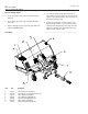
51-3845, 7/04 13 Installation OPERATION SECTION INSTALLATION Initial Installation Follow the instructions for the subframe kit. Install Front Hitch 1. Lift the hitch assembly (C, figure 1) slide onto the slots on tractor (E). Lift back of hitch assembly to frame (D) and install clevis pins (B), clevis pins (F) and hair pins (A). D A E C B Many approved attachments have color coded quick couplers to aid in installation. Match the tractor quick coupler with the like colored attachment quick coupler.
51-3845, 7/04 Installation OPERATION SECTION INSTALLATION F A E C B D E Figure 1 A. Drive Shaft B. Support Bracket C. Front Hitch D. Capscrews, 3/8-16 x 3/4 E. Carriage Bolts and Nuts F. Set Collars Install Long Drive Shaft 1. Slide the drive shaft (A, Figure 1) in from the front. Line up the support bracket (B) with the front hitch (C). Simultaneously line up the locking collar of the drive shaft (A, Figure 12) with the gear drive of the transmission (B). 2.
51-3845, 7/04 15 OPERATION SECTION INSTALLATION Install Brush Head 1. Use tractor lift lever to lower hitch. 2. Position tractor in line with brush head. 3. Drive forward until hitch touches brush head, lift hitch to engage implement. 4. Stop tractor engine, get off tractor, ensure pins snap and engage into hitch. (figure 1.) 5. Connect drive line. 6. Connect cylinder to hitch and hydraulic lines to tractor. 7. Place storage stands in up position. Brush head not shown Closed (In) Figure 1.
OPERATION SECTION OPERATING TIPS Before Operation Operational Check CAUTION – Contact with the sweeper, moving joints or material discharged by the brush can cause serious injury. Operate this implement from the operator’s seat only. Make sure bystanders are well clear of the sweeper and sweeper discharge area before angling or engaging the sweeper. 1. Lubricate all U-joints and driveline components on the sweeper with high-quality, multi-purpose grease. 51-3845, 7/04 5.
51-3845, 7/04 Operating Instructions 4 WD hydraulic right 17 OPERATION SECTION OPERATING TIPS Operating Sweeper Use the tractor lift lever to raise and lower the sweeper. CAUTION – Operate this implement from the operator’s seat only. Do not allow other riders on the machine at any time. CAUTION – Operate this implement at a speed that matches working conditions. Be extremely careful when working on banks or uneven terrain.
OPERATION SECTION OPERATING TIPS Operating Instructions 51-3845, 7/04 Lawn Thatching Leaf Raking NOTE – Your sweeper is provided with a polypropylene brush. Brushes with 1/2 poly– 1/2 wire or full wire sections may damage lawns by pulling out the live grass. Brushes made with wire are not recommended for lawn thatching. Carry the sweeper with implement lift slightly raised to limit contact with the grass. Carry the sweeper with the implement lift slightly raised to limit ground contact.
51-3845, 7/04 Troubleshooting If Material Piles in Front of Sweeper • Decrease travel speed • Increase the engine rpm • Make more than 1 pass • Raise the brush to decease the contact area • Increase the sweeper angle __________________________________________ If Brush Wears Unevenly • Check for material wrapped around the brush • Clean underneath the hood __________________________________________ If Driveline Wears Quickly • Decrease travel speeds • Make more than 1 pass, especially in deep, heavy mate
OPERATION SECTION REMOVING SWEEPER AND HITCH 51-3845, 7/04 Removal/Storage Sweeper & Hitch Removal NOTE – Whenever removed, install clevis pins, hitch pins, clips and hardware into the sweeper and hitch for storage. 1. Install stands in storage position and fully lower the attachment lift. 2. Disconnect the drive shaft by pulling back on the locking collar and then pulling the shaft off. 3. Disconnect hydraulic hoses. Disconnect hairpins and remove clevis pins.
51-3845, 7/04 21 Maintenance MAINTENANCE SECTION DAILY MAINTENANCE CAUTION – Allow only trained personnel to operate or service this implement. Know and understand all precautions before assembly, service or operation. Also read and understand all safety precautions in the tractor operator’s manual. Lubrication Gearbox figure 1 Check gearbox lubricant every 25 hours. 1. When oil is cold, remove the top plug (figure 1). Make sure oil is level with the plug hole. 2.
MAINTENANCE SECTION DAILY MAINTENANCE/BRUSH REPLACEMENT 51-3845, 7/04 Maintenance Daily Maintenance Checks Hardware – Check and tighten all hardware on the sweeper, including factory-installed hardware. Brush Contact – Check brush contact. (See Adjusting Brush Contact Area, page 25.) __________________________________________ Brush Replacement Replace sections when worn to 14 in. (356 mm) in diameter.
51-3845, 7/04 23 Maintenance MAINTENANCE SECTION BRUSH REPLACEMENT 5. Remove the snap ring from the large sprocket (figure 6). 6. Remove the lock hub by removing all set screws and then inserting the screw indicated in figure 7. 7. Remove the sprocket, washer and key from the brush core. 8. Loosen 2 M8 hex nuts that retain the bearing on the bearing end of the core (figure 8). Figure 6 9. Slide the core to the toward the bearing end to allow additional space on the other side. 10.
MAINTENANCE SECTION 51-3845, 7/04 Maintenance BRUSH REPLACEMENT 14. Install new sections by doing the following. a. Number the tubes on the core as 1, 2, and 3 (figure 1). b. Slide the first section onto the core with the drive pins (figure 2) on both sides of tube 1. Make sure that the drive pins face up. NOTE – When using 1/2 poly–1/2 wire sections, place a poly section first and last on the core to prevent damage to the hood, driveline and frame. figure 1 c.
51-3845, 7/04 25 Maintenance MAINTENANCE SECTION ADJUSTING DRIVE CHAIN IDLER/BRUSH PATTERN Adjusting Drive Chain Idler 1. Clean debris off the idler adjustment screw (figure 1) located on the drive end of the brush head. 2. Disconnect the quick release end of the sweeper drive shaft. 3. Raise the sweeper several inches off the ground. 4. Loosen the jam nut. Figure 1 5. While rotating the brush manually, turn the idler screw by hand until it will not tighten any more.
51-3845, 7/04 26 Notes
51-3845, 7/04 27 Parts M26 Series Table of Contents Parts List ............................................................ 28-32 Brush Head ........................................................ 28-29 Hitch ....................................................................... 30 Mounting Hardware ................................................ 31 Sections ..................................................................
PARTS SECTION BRUSHHEAD ASSEMBLY Item 1. 2. 3. 4. 5. 6. 7. 8. 9. 10. 11. 12. 13. 14. 15. 16. 17. 18. 19. 20. 21. 22. 23. 24. 25. 26. 27. 28. 29. 30. 31. 32. 33. 34. 35. Part 01-5847 51-3845, 7/04 Brush Head Qty Description 24 Section, 26, 8 P, Convoluted, Black (4 Ft Broom) 31 Section, 26, 8 P, Convoluted, Black (5 Ft Broom) 06-0433 1 Sprocket, 50B11 x 1 Bore x 1/4 Key 06-0434 1 Sprocket, 50B36, Tapered Bore 06-0435 1 Hub, Taper, 1.
51-3845, 7/04 Brush Head Brush Head 29 PARTS SECTION BRUSHHEAD ASSEMBLY
51-3845, 7/04 Angling Rod PARTS SECTION HITCH ASSEMBLY 22 4 2 21 17 11 20 16 6 10 18 14 8 1 5 3 12 19 13 FINAL INSTALLATION VIEW OF 11-1533 Item Part 1. 2. 3. 4. 5. 6. 7. 8. 9. 10. 11.
51-3845, 7/04 31 PARTS SECTION MOUNTING HARDWARE Kit 11-5133 Mounting Hardware #1709659 (QTY 2) #1709660 (QTY 2) #1960587 (QTY 2) #1924366 (QTY 2) 11-5132 Kit Hydraulic Swing Part # 1725359 1725049 1918452 1725322 1960033 919171 172320 1725318 1725319 173359 1725520 1726321 1726319 Qty 1 1 1 1 1 1 1 1 1 2 2 2 2
PARTS SECTION SECTIONS Item 1.
51-3845, 7/04 33 Appendix M26 Series Table of Contents Hardware and Torque Specifications ......................... 34 Warranty ..............................................................
51-3845, 7/04 Torque Values APPENDIX HARDWARE/TORQUE SPECIFICATIONS Hardware Identification & Torque Specifications Common Hardware Types Torque Specification Chart Hex Head Capscrew FOR STANDARD MACHINE HARDWARE (Tolerance ± 20%) Washer Hardware Grade Lockwasher Carriage Bolt No Marks SAE Grade 2 Hex Nut Size Of Hardware Standard Hardware Sizing 8-32 8-36 10-24 10-32 1/4-20 1/4-28 5/16-18 5/16-24 3/8-16 3/8-24 7/16-14 7/16-20 1/2-13 1/2-20 9/16-12 9/16-18 5/8-11 5/8-18 3/4-10 3/4-16 7/8-9
City Date Delivered to Customer __________ Date Delivered to Dealer ___________ City Zip Phone Form: SWR Rev 4/97 White-Customer Yellow-Dealer Card-Return to Sweepster postage paid State _______________________________________________________ Address _______________________________________________________ Dealer's Name _______________________________________________________ Engine Model _____________________ Engine Make ____________________ Phone Serial Number _____________________ Zip Mo
Warranty Information one year 12 APPENDIX WARRANTY INFORMATION 51-3845, 7/04