Safety Instructions & Operator’s Manual for INTERMEDIATE REAR TINE TILLER SERIES 3 MODEL IR5003B NIR5003B MODEL NUMBER EXPLANATION I R 50 03 MODEL DESIGNATION REAR TINE MODEL I – Intermediate Size Model R – Rear Tine Type Model B ENGINE MODEL SERIES DESIGNATION ENGINE HP 50 – 5 HP Engine (Horse Power) 3 - Series Designation B – Briggs Engine Thank you for buying a SNAPPER product! Your Tiller was designed and built to provide long and satisfactory service.
IMPORTANT SAFETY INSTRUCTIONS WARNING: This powerful machine is capable of amputating hands and feet and can throw objects that can cause injury and damage! Failure to comply with the following instructions may result in serious injury to the operator or other persons. The owner of the tiller must understand these instructions and, furthermore, must allow only persons who understand these instructions to operate tiller.
TABLE OF CONTENTS IMPORTANT SAFETY INSTRUCTIONS................................................... 2 TABLE OF CONTENTS ............................................................................ 3 SECTION 1 - FAMILIARIZATION.............................................................. 4 SECTION 2 - OPERATING INSTRUCTIONS......................................... 5-7 Transmission Positions ............................................................... 5 Pre-Start Checklist..................................
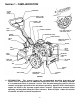
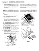
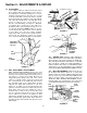
Section 1 - FAMILIARIZATION HANDLEBAR CLUTCH CABLE COVER WHEEL & TINE CONTROL BAIL WHEEL & TINE SHIFT LEVER SHIFT COVER DASH PANEL THROTTLE CONTROL LEFT SIDE SHOWN TO VIEW CHECK PLUG ENGINE AIR FILTER HANDLE BRACKET CHOKE CONTROL DEPTH BAR MAIN CASE GREASE CHECK PLUG ENGINE TINE COVER DRIVE BELT GUARD DRAG SHIELD ENGINE OIL CHECK/FILL PLUG MAIN CASE FILL PLUG OIL DRAIN PLUG TINE STARTER ROPE TIRE & WHEEL WEIGHT BOX TRANSMISSION CHAIN CASE STAND-UP BAR FIGURE 1 1.
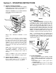
Section 2 - OPERATING INSTRUCTIONS 2.1 BEFORE OPERATING: Be thoroughly familiar with the operation of ALL controls and how to use them BEFORE operating your Tiller. Transmission shifting is done by shifting the WHEEL and TINE SHIFT LEVER into the desired position. Refer to Figure 3. FIGURE 2 When activated, the tines rotate in a rearward (Reverse) direction ONLY.
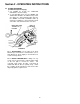
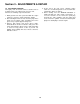
Section 2 - OPERATING INSTRUCTIONS 2.4 ENGINE STARTING PROCEDURE Step 1: Place the WHEEL and TINE SHIFT LEVER in the NEUTRAL position and make sure the WHEEL and TINE CONTROL BAIL is in the released position. LOW MEDIUM HIGH REMOVE SCREW TO ADJUST HANDLEBAR Step 2: For cold starts, move the CHOKE CONTROL on the engine forward into CHOKE position. See Figure 5. HANDLE BRACKET PUSH FORWARD TO CHOKE FIGURE 6 2.6 TRANSPORTING 2.6.
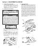
Section 2 - OPERATING INSTRUCTIONS 2.7 TILLING PROCEDURE (Continued from previous page) 3. Set SPEED by moving the THROTTLE CONTROL to desired setting. 4. To start TILLING action, move the WHEEL and TINE SHIFT LEVER to the FWD & TIL position (See Figure 8). Step behind the Tiller and raise the WHEEL and TINE CONTROL BAIL up against the handlebar to start forward movement of the Tiller and rearward rotation of the tines. MOVE SHIFT LEVER TO FWD & TIL POSITION FWD & TIL POSITION FIGURE 8 2.7.
Section 3 - ADJUSTMENTS & REPAIR 3.1 SERVICE PARTS & ASSISTANCE To retain the original quality of your Tiller, use only genuine SNAPPER replacement parts. Specify the model and serial number as found on the nameplate of your Tiller when contacting your SNAPPER Dealer for parts or service assistance. 3.3 TILLER LUBRICATION CHAIN CASE: Check the level of the grease in the chain case at the beginning of each tilling season. Remove clevis pin and cotter pin that secures left hand tire/wheel to axle.
Section 3 - ADJUSTMENTS & REPAIR 3.4 TILLER TINES Your Snapper Tiller has right hand and left hand tines. Replace both tines if blades become bent or are badly worn or otherwise damaged. Use correct Snapper replacement tines. The tines are secured to the tine shaft with a shear bolt, Part No. 2-8725 and Lock Nut Part No. 9-0222 on each side. NOTE: Two extra nuts and two bolts come with tiller. Keep spares on hand in case a bolt shears off or becomes lost while tilling. See Figure 11.
Section 3 - ADJUSTMENTS & REPAIR 4. At the start of the new season, replenish engine crank-case oil and add gasoline to the fuel tank after returning the Tiller to its wheels. 5. Before starting, move the ENGINE CONTROL to STOP and pull rope starter slowly several times. If excessive resistance is felt, remove the spark plug and pull rope starter rapidly to spin the engine and clear oil from the cylinder. Clean and reinstall spark plug before attempting to start the engine. 3.
3 YEAR LIMITED WARRANTY For three (3) years from purchase date for the original purchaser's residential, non-commercial use, SNAPPER, through any authorized SNAPPER dealer will replace, free of charge (except for taxes where applicable), any part or parts found upon examination by the factory at McDonough, Georgia, to be defective in material or workmanship or both.
PRIMARY MAINTENANCE 12
PRIMARY MAINTENANCE 13
PRIMARY MAINTENANCE 14
PRIMARY MAINTENANCE 15
SERVICE NOTES ______________________________________________________________________________ ______________________________________________________________________________ ______________________________________________________________________________ ______________________________________________________________________________ ______________________________________________________________________________ ______________________________________________________________________________ ________________________
SERVICE NOTES ______________________________________________________________________________ ______________________________________________________________________________ ______________________________________________________________________________ ______________________________________________________________________________ ______________________________________________________________________________ ______________________________________________________________________________ ________________________
Safety Instructions & Operator’s Manual for INTERMEDIATE REAR TINE TILLER SERIES 3 MODELS IR5003B & NIR5003B WARNING: The engine exhaust from this product contains chemicals known to the State of California to cause cancer, birth defects or other reproductive harm. COPYRIGHT © 1999 SNAPPER INC. ALL RIGHTS RESERVED MANUAL No. 2-8701 (REV.