Operator’s Manual SW30 Series N ep o ro t fo du r ct io n Walk-Behind Mowers Model Number Description 5900856 5900887 5900899 SW30KAV1852, 52” Cut Walk-Behind Mower SW30KAV2061, 61” Cut Walk-Behind Mower R 5900855 SW30KAV2052, 52” Cut Walk-Behind Mower SW30KAV2661, 61” Cut Walk-Behind Mower 5900964 SW30KAV1848, 48” Cut Walk-Behind Mower 5900547 SW30KAV1948, 48” Cut Walk-Behind Mower 5900548 SW30KAV1952, 52” Cut Walk-Behind Mower 5900549 SW30KAV2152, 52” Cut Walk-Behind Mower 5900550 SW30KA
Thank you for purchasing this quality-built SNAPPER PRO product. We’re pleased that you’ve placed your confidence in the SNAPPER PRO brand. When operated and maintained according to the instructions in this manual, your SNAPPER PRO product will provide many years of dependable service. This manual contains safety information to make you aware of the hazards and risks associated with this machine and how to avoid them.
Table of Contents Operator Safety .................................................. 2 Safety Rules and Information .................................2 Safety Decals ...................................................... 8 Safety Interlock System & Safety Icons..................9 Features & Controls ......................................... 10 Identification Numbers ..........................................10 Control Locations & Functions S/N: 2014523388 & Above ................................
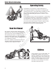
Safety Rules & Information Operating Safety Congratulations on purchasing a superior-quality piece of lawn and garden equipment. Our products are designed and manufactured to meet or exceed all industry standards for safety. Do not operate this machine unless you have been trained. Reading and understanding this operator’s manual is a way to train yourself. Power equipment is only as safe as the operator.
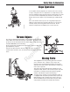
Safety Rules & Information Slope Operation You could be seriously injured if you use this unit on too steep of a slope. Using the unit on a slope that is too steep where you do not have adequate footing and unit traction (and control) can cause you to lose control and possibly slip and fall or roll the unit over. Always mow across slopes, not up and down (you could slip and fall.) Also, note that the surface you are on can greatly impact your ability to safely operate this machine.
Safety Rules & Information Fuel and Maintenance Always disengage all drives, shutoff the engine and remove the key before doing any cleaning, refueling or servicing. Gasoline and its vapors are extremely flammable. Do not smoke while operating or refueling. Do not add fuel while engine is hot or running. Allow engine to cool for at least 3 minutes prior to adding fuel. Do not add fuel indoors, in an enclosed trailer, garage or other enclosed area that is not well ventilated.
Safety Rules & Information Read these safety rules and follow them closely. Failure to obey these rules could result in loss of control of unit, severe personal injury or death to you, or bystanders, or damage to property or equipment. This mowing deck is capable of amputating hands and feet and throwing objects. The triangle in text signifies important cautions or warnings which must be followed. TRAINING PREPARATION R 1.
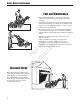
Safety Rules & Information 23. Use care when approaching blind corners, shrubs, trees or other objects that may obscure vision. 24. To reduce fire hazard, keep unit free of grass, leaves & excess oil. Do not stop or park over dry leaves, grass or combustible materials.
Safety Rules & Information SERVICE AND MAINTENANCE To avoid personal injury or property damage, use extreme care in handling gasoline. Gasoline is extremely flammable and the vapors are explosive. N ep o ro t fo du r ct io n Safe Handling of Gasoline 1. Extinguish all cigarettes, cigars, pipes, and other sources of ignition. 2. Use only approved gasoline containers. 3. Never remove the gas cap or add fuel with the engine running. Allow the engine to cool before refueling. 4.
Operator Safety Safety Decals Before operating your unit, read the safety decals. The cautions and warnings are for your safety. To avoid a personal injury or damage to the unit, understand and follow all safety decals. WARNING 1 2 If any safety decals become worn or damaged, and cannot be read, order replacement decals from your local dealer. 3 N ep o ro t fo du r ct io n 4 5 4 R 1 2 2 5 3 3 8 www.SnapperPro.
Operator Safety Safety Icons Safety Interlock System This unit is equipped with safety interlock switches. These safety systems are present for your safety, do not attempt to bypass safety switches, and never tamper with safety devices. Check their operation regularly. Operational SAFETY Checks Test 1 — Engine should NOT crank if: • PTO switch is engaged, OR • Parking brake is not engaged, OR • Forward speed control lever is not in the NEUTRAL position.
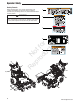
Features and Controls Features and Controls Identification Numbers SA A M PL E North American Models When contacting your authorized dealer for replacement parts, service, or information you MUST have these numbers. Record your model / serial number and engine serial numbers on the space provided for easy access. These numbers can be found in the locations shown. Figure 1. Identification Numbers A.
Features and Controls S/N: 2014523387 & Below A N ep o ro t fo du r ct io n B Figure 2A. Control Locations (S/N: 2014523387 & Below) Control Functions The information below briefly describes the function of individual controls. Starting, stopping, driving, and mowing require the combined use of several controls applied in specific sequences. To learn what combination and sequence of controls to use for various tasks see the OPERATION section.
Features and Controls B Ignition Switch (Electric Start Models) The ignition switch starts and stops the engine, it has three positions: OFF Stops the engine and shuts off the electrical system. RUN Allows the engine to run and powers the electrical system. START Cranks the engine for starting. NOTE: Never leave the ignition switch in the run position with the engine stopped-this drains the battery.
Operation Operation A General Operating Safety Before first time operation: • Be sure to read all information in the Safety and Operation sections before attempting to operate this unit. • Become familiar with all of the controls and how to stop the unit. • Drive in an open area without mowing to become accustomed to the unit. Checks Before Starting B Figure 3. Pre-start Checks A. Fuel Tank Filler Neck B. Engine Oil Dipstick C.
Operation Starting the Engine (Electric Start Engines) 1. Engage the parking brake and make sure that the PTO switch is disengaged and the forward speed control lever is in the NEUTRAL position. 2. NOTE: A warm engine may not require choking. Set the engine throttle control to FULL throttle position. Then fully close the choke by pulling the knob OUT fully. 3. Insert the key into the ignition switch and turn it to START. 4. After the engine starts, gradually open the choke (push knob down fully).
Operation S/N: 2014523387 & Below The cutting height indicators will help you identify the cutting height. A 1. Pull the cutting height adjustment handle (A, Figure 6) up and out of the handle lock position (B) and crank the handle CLOCKWISE to raise the deck to the desired cutting height. Crank the handle COUNTER-CLOCKWISE to lower the deck to the desired cutting height. After the desired cutting heights are achieved position the cutting height adjustment handles into the handle lock position. 2.
Operation Driving The Mower To Slow or Stop Machine Before attempting to drive the mower make sure you have read the Features and Controls section and understand the location and function of the controls. 1. Gently squeeze both reverse speed control levers evenly to slow the machine. 2. Continuing to squeeze the reverse speed control levers will stop the machine. 3. Once the machine is stopped, firmly depress the neutral return pedal to place the transmissions in neutral. 4. Engage the parking brake.
Operation Mowing Before mowing, set the cutting height as described in CUTTING HEIGHT ADJUSTMENT. 1. Engage the parking brake. Make sure the PTO switch is disengaged and the forward speed control lever is in the NEUTRAL position 2. Start the engine (see Starting The Engine). 3. Set the throttle to FULL. 4. Engage the PTO by pulling up on the PTO switch. 5. Begin mowing. See Mowing Recommendations for tips on mowing patterns, lawn care, and trouble shooting information. 6.
Operation When and How Often to Mow The time of day and condition of the grass greatly affect the results you’ll get when mowing. For the best results, follow these guidelines: 1. Mow when the grass is between three and five inches high. 2. Mow with sharp blades. Short clippings of grass one inch or shorter decompose more quickly than longer blades. Sharp mower blades cut grass cleanly and efficiently, preventing frayed edges which harm the grass. 3. Mow at time of day when the grass is cool and dry.
Operation Proper Mulching Mulching consists of a mower deck which cuts and recuts clippings into tiny particles and which then blows them down INTO the lawn. These tiny particles decompose rapidly into by-products your lawn can use. UNDER PROPER CONDITIONS, your mulching mower will virtually eliminate noticeable clippings on the lawn surface. NOTE: When mulching under heavy cutting conditions, a rumbling sound may be present and is normal.
Regular Maintenance Regular Maintenance Maintenance Schedule The following schedule should be followed for normal care of your mower and mower deck. You will need to keep a record of your operating time. Determining operating time is easily accomplished by observing the elapsed time recorded by the hour meter.
Regular Maintenance Checking / Adding Fuel WARNING To add fuel: Fuel and its vapors are extremely flammable and explosive. Fire or explosion can cause severe burns or death. 1. Remove the fuel cap (E, Figure 9). 2. Fill the tank to the bottom of the filler neck. This will allow for fuel expansion. NOTE: Do not overfill. Refer to your engine manual for specific fuel recommendations. 3. Install and hand tighten the fuel cap. Fuel Filter Change Oil & Filter R 1. Warm engine by running for a few minutes.
Regular Maintenance Lubrication Lubricate the unit at the locations shown in Figures 10 & 11 as well as the following lubrication points. Generally, all moving metal parts should be oiled where contact is made with other parts. Keep oil and grease off belts and pulleys. Remember to wipe fittings and surfaces clean both before and after lubrication.
Regular Maintenance Check / Fill Transmission Oil Oil Type: 20W-50 conventional detergent motor oil. 1. Check the oil level when the unit is cold. Locate the transmission oil reservoirs (A, Figure 12) located on the handle bar assembly. The oil should be up to the “FULL COLD” mark (B). If the oil is below this level, proceed to step 2. A 2. Before removing the reservoir caps, make sure the area around the reservoir cap and fill neck of the reservoir is free of dust, dirt, or other debris.
Regular Maintenance Servicing The Mower Blades Removing the Mower Blade CAUTION Avoid injury! Mower blades are sharp. Always wear gloves when handling mower blades or working near blades. 1. To remove the mower blade, use a 1” wrench on the flats of the spindle shaft and remove the mower blade mounting bolt with a 15/16” wrench (Figure 14). 2. If there are no flats on the spindle shaft, wedge a wooden block between the mower blade and the mower deck housing to keep the mower blade from turning. Figure 14.
Regular Maintenance Sharpening the Mower Blade A CAUTION Avoid injury! Mower blades are sharp. • Always wear gloves when handling mower blades or working near blades. • Always wear safety eye protection when grinding. 1. Sharpen the mower blades with grinder, hand file, or electric blade sharpener. 2. Sharpen the mower blade by removing an equal amount of material from each end of the mower blade. 3. Keep the original bevel (A, Figure 17) when grinding. DO NOT change the mower blade bevel. 4.
Regular Maintenance Neutral Adjustment If the unit “creeps” while the forward speed control lever is locked in the NEUTRAL position, then it may be necessary to adjust the adjustment linkage rods A NOTE: Perform this adjustment on a hard, level surface such as a concrete floor. B C B A Figure 20. Neutral Adjustment A. Ball Stud B. Nuts C. Adjustment Linkage Rod N ep o ro t fo du r ct io n 1. Disengage the PTO, engage the parking brake and turn off the engine. 2.
Regular Maintenance (S/N: 2014523388 & Above) To Reduce the Speed of the Faster Wheel: B A R N ep o ro t fo du r ct io n There are three (3) nuts (A, Figure 22) on the linkage rod (B). The first two are to be used together to turn the rod and the third is used to lock the rod in place. 1. Loosen the jam nut that locks against the clevis. 2. Turn the linkage rod COUNTER-CLOCKWISE to reduce the speed. 3. Retighten the jam nut when adjustment is complete. Figure 22.
Regular Maintenance Parking Brake Adjustment 1. Disengage the PTO, stop the engine, remove the ignition key, and engage the parking brake. 2. Locate the brake springs (A, Figure 23) underneath the rear of the machine. 3. With the parking brake engaged, measure the compressed spring length of the brake spring. The spring should be 2-1/2” (6,35 cm) when compressed. If not, position the lock nut until the measurement equals 2-1/2” (6,35 cm). 4.
Regular Maintenance Deck Leveling Adjustment S/N: 2014523388 & Above Figure 24. 2 x 4 Locations R N ep o ro t fo du r ct io n 1. Park the machine on a flat, level surface. Disengage the PTO, stop the engine and engage the parking brake. Rear tires must be inflated to 15 psi (1,03 bar). 2. Remove the mower deck guard. 3. Adjust the mower deck height to the 4” (10,2 cm) position. 4. Place the 2 X 4 blocks under each corner of the mower deck with the 3-1/2” sides being vertical. See Figure 24. 5.
Regular Maintenance Deck Leveling Adjustment S/N: 2014523387 & Below A 1. Park the machine on a flat, level surface. Disengage the PTO, stop the engine and engage the parking brake. Rear tires must be inflated to 15 psi (1,03 bar). 2. Pull the cutting height adjustment handle (A, Figure 27) up and out of the handle lock position (B) and adjust the deck to the 3” (7,6 cm) position. 3. Repeat process for other side of machine. NOTE: Both sides of the deck must be adjusted to the same height.
Regular Maintenance Mower Belt Replacement E B NOTICE A E To avoid damaging belts, do NOT pry belts over pulleys. 1. Park the unit on a smooth, level surface such as a concrete floor. Disengage the PTO, engage the parking brake, turn off the engine, and remove the ignition key. 2. Lower the mower deck to its lowest cutting position and remove the mower deck guard. 3.
Regular Maintenance Transmission Drive Belt Replacement 11. Reconnect the PTO clutch wire harness to the PTO clutch. 12. Using a new wire tie secure the PTO clutch wire harness to the frame and away from moving components. 13. Reinstall the PTO drive belt. 14. Using the hardware that was previously removed reinstall the skid plates to the engine deck. N ep o ro t fo du r ct io n 1. Park the unit on a smooth, level surface such as a concrete floor.
Regular Maintenance Reverse Speed Control Levers Comfort Adjustment (S/N: 2014522399 & Below) A B The amount of pressure necessary to depress the Reverse Speed Control Levers (A, Figure 33) can be adjusted to meet the comfort needs of the operator. 1. Disengage the PTO, engage the parking brake and turn off the engine. 2. To increase the amount of pressure necessary to depress the Reverse Speed Control Levers turn the lock nut (B) CLOCKWISE until the desired comfort level is achieved.
Regular Maintenance Battery Maintenance A This unit is equipped with a maintenance-free BCIU1 battery. B Cleaning the Battery and Cables 1. Disconnect the cables from the battery, negative [-] cable first (A, Figure 35). 2. Clean the battery terminals and cable ends with a wire brush until shiny. 3. Reinstall the battery and reattach the battery cables, positive [+] cable first (B). 4. Coat the cable ends and the battery terminals with petroleum jelly or non-conducting grease.
Regular Maintenance Jump Starting With Auxiliary (Booster) Battery Battery Service WARNING • Keep open flame and sparks away from the battery; the gasses coming from it are highly explosive. • Ventilate the battery well during charging. Checking Battery Voltage A voltmeter can be used to determine the condition of the battery. When engine is off, the voltmeter shows battery voltage, which should be 12 volts.
Regular Maintenance THIS HOOK-UP FOR NEGATIVE GROUND VEHICLES To Starter Switch To Starter Switch Jumper Cable Starting Vehicle Battery Discharged Vehicle Battery Jumper Cable To Ground Engine Block Figure 36. Jump Starting N ep o ro t fo du r ct io n MAKE CERTAIN VEHICLES DO NOT TOUCH WARNING Any procedure other than the proceeding could result in: R 1. Personal injury caused by electrolyte squirting out of the battery vents. 2. Personal injury or property damage due to battery explosion. 3.
Regular Maintenance Storage WARNING Temporary Storage (30 Days Or Less) Fuel and its vapors are extremely flammable and explosive. Fire or explosion can cause severe burns or death. Remember, the fuel tank will still contain some gasoline, so never store the unit indoors or in any other area where fuel vapor could travel to any ignition source. Fuel vapor is also toxic if inhaled, so never store the unit in any structure used for human or animal habitation.
Troubleshooting Troubleshooting Troubleshooting Chart WARNING While normal care and regular maintenance will extend the life of your equipment, prolonged or constant use may eventually require that service be performed to allow it to continue operating properly. The troubleshooting guide below lists the most common problems, their causes and remedies. See the information on the following pages for instructions on how to perform most of these minor adjustments and service repairs yourself.
Troubleshooting Mower Troubleshooting Continued. Problem Cause Remedy 1. 2. 3. 4. Transmission release lever(s) in “disengaged” position. Belt is broken. Drive belt slips. Brake is not fully released. 1. Move transmission release lever(s) to the “engaged” position. 2. See Drive Belt Replacement. 3. See problem and cause below. 4. See authorized service dealer 1. 2. Pulleys or belt greasy or oily. Tension too loose. 3. Belt stretched or worn. 1. Clean as required. 2. Adjust spring tension.
Troubleshooting Troubleshooting Common Cutting Problems Problem Cause Remedy Streaking. 1. 2. 3. 4. 5. 6. Blades are not sharp. Blades are worn down to far. Engine speed is too slow. Ground speed is too fast. Deck is plugged with grass Not overlapping cutting rows enough. Not overlapping enough when turning. 1. Sharpen your blades. 2. Replace your blades. 3. Always mow at full throttle. 4. Slow down. 5. Clean out the mower. 6. Overlap your cutting rows. 1. Roll or level the lawn. 2.
Specifications TRANSMISSIONS Specifications 18 Gross HP† Kawasaki Manual Start S/N: 2014600769 & Below: Hydro-Gear ZJ-KMEE-3B5A-1RLX (RH) Hydro-Gear ZJ-GMEE-3B5A-1RLX (LH) S/N: 2014600770 & Above: Hydro-Gear ZJ-KMFE-3B5B-1RLX (RH) Hydro-Gear ZJ-GMFE-3B5B-1RLX (LH) Make Model Displacement Oil Capacity Type Hydraulic Fluid Speeds @ 3400 rpm Note: Specifications are correct at time of printing and are subject to change without notice. ENGINE: Kawasaki FX541V 36.8 Cu. in (603 cc) 1.8 US qt.
42 www.SnapperPro.com 2 ALIGN THIS EDGE WITH A VERTICAL SURFACE (TREE, POLE, FENCE POST, BUILDING, ETC) EGREE 3 COMPARE THE ANGLE OF THE FOLD TO THE ANGLE OF THE SLOPE 1. Fold this page along the dotted line indicated above. 2. Align the left edge of this guide with a vertical tree, a power line pole, a fence post, or any vertical structure. 3. Compare the angle of the fold with the angle of the hill.
N ep o ro t fo du r ct io n R Notes
BRIGGS & STRATTON PRODUCTS WARRANTY POLICY September 2012 LIMITED WARRANTY Briggs & Stratton warrants that, during the warranty period specified below, it will repair or replace, free of charge, any part that is defective in material or workmanship or both. Transportation charges on product submitted for repair or replacement under this warranty must be borne by purchaser. This warranty is effective for and is subject to the time periods and conditions stated below.
California, U.S. EPA, and Briggs & Stratton Corporation Emissions Control Warranty Statement Your Warranty Rights And Obligations The California Air Resources Board, U.S. EPA, and Briggs & Stratton (B&S) are pleased to explain the emissions control system warranty on your Model Year 2012--2013 engine/equipment. In California, new small off-road engines and large spark ignited engines less than or equal to 1.0 liter must be designed, built, and equipped to meet the State’s stringent anti-smog standards.
Operator’s Manual SW30 Series R N ep o ro t fo du r ct io n Walk-Behind Mowers BRIGGS & STRATTON POWER PRODUCTS GROUP, LLC 5375 NORTH MAIN STREET MUNNSVILLE, NY 13409 800 933 6175