Operator's Manual REAR ENGINE RIDING MOWER SERIES 24 Model No. Description 2811524BV 2812524BVE 3014524BVE 3317524BVE ! R N ep o ro t fo du r ct io n 7800784 7800785 7800786 7800787 Manual No. 7104742 (Rev.
Thank You for purchasing this quality-built Snapper product. We’re pleased that you placed your confidence in the Snapper brand. When operated and maintained according to the instructions in this manual, your Snapper product will provide many years of dependable service. This manual contains safety information to make you aware of the hazards and risks associated with the machine and how to avoid them.
Table of Contents Operator Safety . . . . . . . . . . . . . . . . . . . . . . . . . . . . . . . . . . . . . . . . . . . . . . . .4 Features and Controls . . . . . . . . . . . . . . . . . . . . . . . . . . . . . . . . . . . . . . . . . . .9 Operation . . . . . . . . . . . . . . . . . . . . . . . . . . . . . . . . . . . . . . . . . . . . . . . . . . .10 Before Starting . . . . . . . . . . . . . . . . . . . . . . . . . . . . . . . . . . . . . . . . . . . . . . . . . . . .10 Operator Seat Adjustment . . . . . .
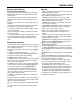
Operator Safety ! WARNING: This powerful cutting machine is capable of amputating hands and feet and can throw objects that can cause injury and damage! Failure to comply with the following SAFETY instructions could result in serious injury or death to the operator or other persons. The owner of the machine must understand these instructions and must allow only persons who understand these instructions to operate machine.
Operator Safety Protection against Tipovers Safe Handling of Gasoline Operation 1. Mount and dismount machine from left side. Keep clear of discharge opening at all times. 2. Start engine from operator’s seat, if possible. Make sure blades are OFF and parking brake is set. 3. DO NOT leave machine with engine running. STOP engine, STOP blades, SET brake, and Remove key before leaving operators position of any reason. 4. DO NOT operate machine unless properly seated with feet on feet rests or pedal(s). 5.
Operator Safety Towing Maintenance 1. Tow only with a machine that has a hitch designed for towing. DO NOT attach towed equipment except at the hitch point. 2. Follow the manufacturer’s recommendation for weight limits for towed equipment and towing on slopes. 3. DO NOT allow children or others on towed equipment. 4. On slopes, the weight of the towed equipment may cause loss of traction and loss of control. 5. Travel slowly and allow extra distance to stop.
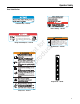
Operator Safety Decal Identification Remove Battery - 7101109 Before Starting - 7101112 Amputation and thrown objects hazard • Keep hands and feet away from deck. • Do not operate mower unless discharge chute or entire grass catcher is in its proper place. N ep o ro t fo du r ct io n 7101110 WARNING Fire Hazard. Operation of this equipment may create sparks that can start fires around dry vegetation. A spark arrestor may be required.
Operator Safety 7104796 Reverse Lockout - 7104796 7103219 Parking Brake - 7103219 CAUTION Fire Hazard • Do IMPORTANT 7104797 7105102 N ep o ro t fo du r ct io n Use only rechargeable valve regulated (sealed) non-spillable batteries in this product. Battery must be factory approved part or equivalent. Do not overcharge. not overfill tank. tank before standing unit on end.
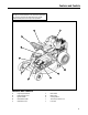
Features and Controls IMPORTANT The figures and illustrations in this manual are provided for reference only and may differ from your specific model. Contact your dealer if you have questions. J I G F A B R E N ep o ro t fo du r ct io n H C D Features and Controls A. B. C. D. E. Engine Speed Control Cutting Height Lever Ignition Switch Clutch/Brake Pedal Park Brake Latch F. G. H. I. J.
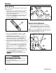
Operation Before Starting Make the following checks and perform the service required before each start-up: 1. Check the tire pressure; add or release air as needed to bring pressure to 15 PSI in front and 12 PSI in rear. 2. Check guards, deflectors and covers to make sure all are in place and securely tightened. 3. Check engine oil and add oil as needed to bring level up to the FULL mark (A, Figure 1). Refer to the engine manual for oil specifications.
Operation Starting and Operation Engine (Electric Start) A IMPORTANT: When the ignition key is turned to “START”, the engine will turn over, but will not start unless the Clutch/Brake pedal is pressed all the way down, and the Blade Lever is in the “OFF” position. The operator should be in the seat. Start the engine as follows: 1. Move the transmission shift lever to the (N) Neutral position. Refer to the section entitled “Wheel Drive”.
Operation Starting and Operation (Continued) A Engine (Electric Start) (Continued) 8. Should the battery be too weak to start the engine, refer to the Section entitled “Engine (Manual Start)” to manually start the electric start engines. 9. On Model 3317524BVE, the engine is equipped with a fuel shut-off solenoid. If the battery is dead, the engine can be started with the recoil back-up starter if the engine speed control is in the choke position (HOT engine or COLD engine).
Operation ! ! WARNING Once blade is disengaged, it should come to a complete stop in 3 seconds or less. If the blade continues to rotate after 3 seconds, the blade brake must be adjusted. Refer to Section “BLADE BRAKE ADJUSTMENT” for adjustment procedures or return machine to an authorized dealer for adjustment. DO NOT CONTINUE to operate machine until blade brake is adjusted and functioning properly. ! ! WARNING DO NOT operate blades in reverse. STOP BLADES.
Operation ! ! WARNING DO NOT leave the machine with the engine running. STOP Blade. STOP engine. Shift to neutral and engage park brake. Remove key. Mower Blade 1. Stop the mower blade by releasing the blade pedals (A, Figure 15) or moving the blade lever (B) rearward to the “OFF” position. B Stopping - Engine, Wheel Drive, Blade Engine 1. Stop the engine by turning the key (A, Figure 13) to the “OFF” position.
Operation Stopping - Engine, Wheel Drive, Blade (Continued) Cutting Height Adjustment 1. Adjust the cutting height by raising or lowering the deck lift lever (A, Figure 18) into the desired height of cut notch (B). Park Brake 1. To set the park brake, press the clutch/brake pedal (A, Figure 16) all the way down, slide the park brake latch (B) all the way in to the engaged position, and release the clutch/brake pedal. A detent in the park brake latch will keep the park brake engaged.
Operation Reverse Lockout Mechanism Data indicates that tragic back-over accidents occur each year. These accidents usually involve unsupervised children. Many times these children have been given rides on the machine and have been trained to view this potentially dangerous piece of machinery as fun rather than being taught how to avoid danger. 1. Stop the machine. Stop the blade. 2. Depress and hold the Override Lever. 3. Depress and hold the Blade Pedals. Release the Override Lever. 4.
Maintenance Maintenance Chart ENGINE Every 8 Hours or Daily First 5 Hours Check safety interlock system Change engine oil Clean debris off tractor and mower deck Every 8 Hours or Daily Clean debris from engine compartment Check engine oil level Every 25 Hours or Annually * Every 25 Hours or Annually * Check tire pressure Clean engine air filter and pre-cleaner ** Check mower blade stopping time Every 50 Hours or Annually * Check tractor/mower for loose hardware Change engine oil Every 50 Ho
Maintenance ! WARNING ! DO NOT attempt any adjustments, maintenance, service or repairs with the engine running. STOP engine. STOP blade. Engage parking brake. Remove key. Remove spark plug wire from spark plug and secure away from plug. Engine and components are HOT. Avoid serious burns, allow all parts to cool before working on machine. Fuel Filler Cap must be closed securely to prevent fuel spillage. Introduction Change Engine Oil The engine is equipped with a dual element air cleaner.
Maintenance ! ! WARNING DO NOT attempt any adjustments, maintenance, service or repairs with the engine running. STOP engine. STOP blade. Engage parking brake. Remove key. Remove spark plug wire from spark plug and secure away from plug. Engine and components are HOT. Avoid serious burns, allow all parts to cool before working on machine. Fuel Filler Cap must be closed securely to prevent fuel spillage.
Maintenance Safety Interlock System Checks ! WARNING Check Engine ! DO NOT operate machine if any safety interlock or safety device is not in place and functioning properly. DO NOT attempt to defeat, modify or remove any safety device. IMPORTANT: When the cover is removed, you are viewing the carburetor side of the air filter, which will appear clean. Remove the filter and pre-cleaner for inspection. A C N ep o ro t fo du r ct io n Engine must not start if: 1.
Maintenance ! WARNING ! DO NOT attempt any adjustments, maintenance, service or repairs with the engine running. STOP engine. STOP blade. Engage parking brake. Remove key. Remove spark plug wire from spark plug and secure away from plug. Engine and components are HOT. Avoid serious burns, allow all parts to cool before working on machine. Fuel Filler Cap must be closed securely to prevent fuel spillage.
Maintenance ! WARNING ! DO NOT attempt any adjustments, maintenance, service or repairs with the engine running. STOP engine. STOP blade. Engage parking brake. Remove key. Remove spark plug wire from spark plug and secure away from plug. Engine and components are HOT. Avoid serious burns, allow all parts to cool before working on machine. Fuel Filler Cap must be closed securely to prevent fuel spillage. 2.
Maintenance ! ! WARNING DO NOT attempt any adjustments, maintenance, service or repairs with the engine running. STOP engine. STOP blade. Engage parking brake. Remove key. Remove spark plug wire from spark plug and secure away from plug. Engine and components are HOT. Avoid serious burns, allow all parts to cool before working on machine. Fuel Filler Cap must be closed securely to prevent fuel spillage.
Maintenance ! WARNING ! DO NOT attempt any adjustments, maintenance, service or repairs with the engine running. STOP engine. STOP blade. Engage parking brake. Remove key. Remove spark plug wire from spark plug and secure away from plug. Engine and components are HOT. Avoid serious burns, allow all parts to cool before working on machine. Fuel Filler Cap must be closed securely to prevent fuel spillage. ! ! WARNING DO NOT operate machine until blade brake is adjusted and functioning properly.
Maintenance ! ! WARNING DO NOT attempt any adjustments, maintenance, service or repairs with the engine running. STOP engine. STOP blade. Engage parking brake. Remove key. Remove spark plug wire from spark plug and secure away from plug. Engine and components are HOT. Avoid serious burns, allow all parts to cool before working on machine. Fuel Filler Cap must be closed securely to prevent fuel spillage.
Maintenance ! WARNING ! DO NOT attempt any adjustments, maintenance, service or repairs with the engine running. STOP engine. STOP blade. Engage parking brake. Remove key. Remove spark plug wire from spark plug and secure away from plug. Engine and components are HOT. Avoid serious burns, allow all parts to cool before working on machine. Fuel Filler Cap must be closed securely to prevent fuel spillage.
Maintenance ! ! WARNING DO NOT attempt any adjustments, maintenance, service or repairs with the engine running. STOP engine. STOP blade. Engage parking brake. Remove key. Remove spark plug wire from spark plug and secure away from plug. Engine and components are HOT. Avoid serious burns, allow all parts to cool before working on machine. Fuel Filler Cap must be closed securely to prevent fuel spillage. 4.
Maintenance ! ! WARNING DO NOT attempt any adjustments, maintenance, service or repairs with the engine running. STOP engine. STOP blade. Engage parking brake. Remove key. Remove spark plug wire from spark plug and secure away from plug. Engine and components are HOT. Avoid serious burns, allow all parts to cool before working on machine. Fuel Filler Cap must be closed securely to prevent fuel spillage. 7. Reinstall the blade. Torque the blade mounting bolts to the recommended range of 30 to 40 ft. lbs.
Maintenance ! WARNING ! DO NOT attempt any adjustments, maintenance, service or repairs with the engine running. STOP engine. STOP blade. Engage parking brake. Remove key. Remove spark plug wire from spark plug and secure away from plug. Engine and components are HOT. Avoid serious burns, allow all parts to cool before working on machine. Fuel Filler Cap must be closed securely to prevent fuel spillage. 9. Reinstall the idler removed in Step 8.
Maintenance ! ! WARNING DO NOT attempt any adjustments, maintenance, service or repairs with the engine running. Stop engine. Stop blade. Engage parking brake. Remove key. Remove spark plug wire from spark plug and secure away from plug. Engine and components are HOT. Avoid serious burns, allow all parts to cool before working on machine. Fuel Filler Cap must be closed securely to prevent fuel spillage. DO NOT attempt to charge the battery while it is installed on the machine. 3.
Maintenance Battery Charging A. Place the battery in a well-ventilated area. B. Connect a 12-volt constant-voltage battery charger to the battery terminals; RED to positive (+) and BLACK to negative (-) terminal. C. Charge the battery for 2 to 4 hours. ! WARNING ! The battery on this unit requires the use of a constant voltage (CV) battery charger designed for valve regulated (sealed) non-spillable batteries. Attempting to use a standard battery charger may result in damage to the battery.
Troubleshooting PROBLEM PROBABLE CAUSE 1. Fill fuel tank with fresh fuel to proper level. 2. Move choke control to “CHOKE” position. 3. Place spark plug wire onto spark plug. 4. Contact authorized dealer. 5. Engage park brake. 6. Turn ignition switch to the RUN position. 1. Fill fuel tank with fresh fuel to proper level. 2. Move choke control to “CHOKE” position. 3. Place spark plug wire onto spark plug. 4. Contact authorized dealer. 5. Engage park brake. 6. Replace with new 20 AMP fuse. 7.
Troubleshooting PROBLEM PROBABLE CAUSE CORRECTIVE ACTION Rider Will Not Move Or Loss of Traction 1. Drive disc worn or damaged. 2. Rubber drive disc is not tracking properly on drive disc. 3. Tapered axle bolt and nut missing. 4. Axle bearing seized. 5. Insufficient lubrication in chain case or transmission/differential. 1. Blade engagement lever in the “OFF” position. 2. Mower belt slipping. 3. Cutting blade is dull, worn or damaged. 1. Uneven tire pressure. 1. Replace drive disc. 2.
Warranty BRIGGS & STRATTON POWER PRODUCTS GROUP, L.L.C. OWNER WARRANTY POLICY LIMITED WARRANTY Briggs & Stratton Power Products Group, LLC will repair and/or replace, free of charge, any part(s) of the equipment that is defective in material or workmanship or both. Briggs & Stratton Corporation will repair and/or replace, free of charge, any part(s) of the Briggs and Stratton engine* (if equipped) that is defective in material or workmanship or both.
N ep o ro t fo du r ct io n R Slope Guide 35
REAR ENGINE RIDING MOWER SERIES 24 Product Specifications 2811524BV 2812524BVE 3014524BVE 3317524BVE 28 28 30 33 1.5 - 4.0 1.5 - 4.0 1.5 - 4.0 1.5 - 4.0 5-Spd Disc 5-Spd Disc 5-Spd Disc 5-Spd Disc 1.0-4.6 / 0-1.9 1.0-4.6 / 0-1.9 1.0-4.6 / 0-1.9 1.0-4.6 / 0-1.9 11.5 12.5 14.5 17.