SNOW CAB #1694921 FOR Regent, LT 200 Series, 500 Series Lawn Tractors, 2500 Series Lawn Tractors PARTS LIST – ASSEMBLY INSTRUCTIONS IMPORTANT ! READ THIS MANUAL CAREFULLY AND KEEP FOR FUTURE REFERENCE CAUTION ! REMOVE THE VINYL PANELS FOR TRANSPORT IN AN OPEN TRUCK OR TRAILER WARNING ! THIS CAB WILL NOT PROTECT OPERATOR FROM INJURIES CAUSED BY ROLLOVER, COLLISION, OR OTHER ACCIDENTS 11574506 1
WARNING This cab is designed to provide foul weather protection only. It does not provide protection from noise, exhaust fumes, chemicals or injury from collision, roll-over or other accidents. 1. Do not operate machine in confined areas without proper ventilation 2. Thoroughly check area of operation before using machine 3. The cab adds height to the machine.
For Replacement Parts and Accessories Contact: Original Tractor Cab Co., Inc. P.O. Box 97 6849 W. Front St. Arlington, IN 46104 Phone 765-663-2214 Fax 765-663-2101 Email Sales@originalcab.com Visit us on the web to see our other products. www.originalcab.com Cabs for Lawn Tractors, Garden Tractors, Compact Tractors, Snow Blowers, Utility Vehicles Sunshades for Tractors, Mowers, & Utility Vehicles Storage Covers for Lawn and Garden equipment. . LIMITED WARRANTY COVERED BY WARRANTY ORIGINAL TRACTOR CAB CO.
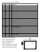
Carton Contents: Snow Cab #1694921 Key # 1 2 3 4 5 6 7 8 9 10 11 12 13 14 15 16 17 18 19 20 21 22 23 Part # 11594 11593 11595 11596 10004 10002 10003 11597 11598 10750 10751 11050 11051 10001 11600 11599 10749-B 10000 11601 11603 11602 11604 9820 11605 786 788 1514 730 4580 1093 2945 60182 4902 Qty.
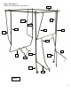
Step 1; See Figure 1: Identify the steel parts by using Figure 1.
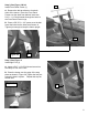
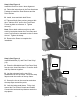
Step 2; See Figure 2 & 2A: Install Front Panel Frame (1) 1 A. Remove the bolt at reference A on both sides of the tractor. Place the Front Panel Frame over the dash from behind. Insert two 5/16” x 1 1/4” bolt inwards through the holes in the Front Panel Frame Legs. B. Place a 5/8” O.D. x 1/2” spacer over the bolt. Insert the bolts into the holes at reference A. Tighten just enough to keep the frame upright. A Figure 2 Figure 2A A Step 3; See Figure 3: Install right Foot (1) A.
Step 4; See Figure 4: Install right & left Front Posts (5) and right & left Top Frame Braces (6 & 7). Note: Bent ends of Top Frame Braces will point rearwards and lay flat when properly installed. 5 7 A. Insert a 1/4” x 3/4” bolt forward through the tab on the post, the end of the Front Panel Frame and then the lower end of the Top Frame Brace. Add a nut. Tighten just enough to hold the braces up. 6 B.
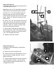
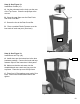
Step 6; See Figure 6: Install right and left Rear Posts (10 & 11) and right and left Rear Boxing Posts (12 & 13). 11 NOTE: When properly installed Rear Post latch plates will face forward with the notch to the outside . A. Insert a 1/4” x 3/4” bolt outwards through the Rear Cross Bar, right Rear Post and then the right Boxing Post,. Add a nut. Tighten enough to keep the parts upright. B. Repeat step 6A on the left side with left Posts.
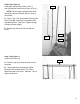
Step 8: See Figure 8: Install the Doors for frame / door alignment. A. Follow the instructions in the Door Hardware Package to install the Door Bottoms and the Door Latches. B. Install, close and latch both Doors. C. Tighten all bolts from previous steps at this time. Add two 5/16” nuts to the Front Panel Frame leg bolts at reference A. Tighten securely. Note: If door latch rod does not line up with notch in latch plate loosen the Foot clamp and move Foot forward or rearward to raise or lower the rod.
Step 10: See Figure 10: Install Rear Curtain (15). A. Lay the rod sewn into the vinyl over the rear of the Top Frame. Close the snap flaps at the corners. B. Close the snap flaps over the Rear Posts and Rear Cross Bar. C. Secure the ties to the Rear Cross Bar. D. Place a notched Plastic Protector over the bent ends of each rear post. (See inset) 15 Step 10: See Figure 10: Install Doors and Top (18). Figure 10 18 A. Install doors per the instructions in the door hardware package.