Safety Instructions & Operator's Manual for PRO HYDRO WALK BEHIND MOWERS MID-SIZE SERIES 1 POWER UNIT MOWER MODELS UNIT MODELS SPLH141KW SPLH171KW SPLH151KH SPLH141KWE SPLH221KHE SP360 SP480 SPA360 SPA480 SPA520 SPA610 Model SPLH141 KW shown MODEL NUMBER IslPll II EXPLANATION II1 I KWl MODE'OES,GNAT,ON J I MODEL TYPE I MODEL OPTION DRIVE SYSTEM TYPE S - Snapper Commercial P - Pro Mid Size Model Model L - Loop Type Handle Model H - Hydro Drive System A - Adjustable Cutting Deck ENGINE
IMPORTANT SAFETY INSTRUCTIONS WARNING: This powerful cutting machine is capable of amputating hands and feet and can throw objects that can cause injury and damage! Failure to comply with the following SAFETY instructions could result in serious injury or death to the operator or other persons. The owner of the machine must understand these instructions and must allow only persons who understand these instructions to operate machine.
IMPORTANT SAFETY INSTRUCTIONS OPERATION 1. 2. 3. 4. 5. 6. 7. A MAINTENANCE 1. DO NOT store machine or fuel container inside where fumes may reach an open flame, spark or pilot light such as in a water heater, furnace, clothes dryer or other gas appliance. Allow engine to cool before storing machine in an enclosure. Store fuel container out of the reach of children in a well ventilated, unoccupied building. 2.
TABLE OF CONTENTS IMPORTANT SAFETY INSTRUCTIONS ................................................................................... TABLE OF CONTENTS ................................................................................................................ SECTION 1 - FAMILIARIZATION SECTION 2 - CONTROLS ................................................................................................. ...................................................................................................
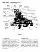
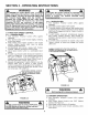
SECTION 1 - FAMILIARIZATION RIGHT HAND TRACTION CONTROL OPERATOR'S SPEED CONTROL LEVER LEFT HAND TRACTION CONTROL BLADE CLUTCH CONTROLSWITCH PRESENCE SPEED CONTROL(OPC) FILLER CAP NEUTRAL LATCH LEVER KEY SWITCH FILL/CHECK HYDRAULIC (Hydraulic CAP FILTER Reservoir) PUMPS(Not Shown)_ REAR TIRES DECK HEIGHT COVER RETAINING KNOBS FUEL SHUT-OFF VALVE (Not Shown) HYDRAULIC DRIVE MOTOR (Behind Each Rear Wheel) WHEEL ASSEMBLY FRONT TIRES DISCHARGE DEFLECTO R COVER MUFFLER DECK (48"Shown) FIGU
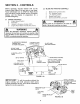
SECTION 2 - CONTROLS 2.2 Before operating, become familiar with all the controls (See Figure 2.1A) and how to use them. Know beforehand how to STOP the Right Hand and Left Hand Traction Wheel Drives, the Mower Blades, and the Engine in preparation for a possible emergency. 2,1 BLADE AND TRACTION CONTROLS 1. 2. 3. 4. 5. ENGINE CONTROLS A. Engine Speed Control B. Keyswitch C. Operator's Presence Control (OPC) D. Engine Recoil Starter Handle (Not shown) Blade Clutch Control Switch R.H. Steering Control L.
SECTION 3 - OPERATING 3.1 PRE-START INSTRUCTIONS CHECKLIST WARNING IMPORTANT: Before starting your SNAPPER Pro Hydro machine, the hydraulic reservoir and engine MUST be filled to the proper level with oil. Use approved fuel container. DO NOT smoke near open fuel container. DO NOT fill fuel tank indoors or when engine is running. Allow engine to cool for at least ten minutes before refilling. Wipe off any spilled fuel before starting engine. DO NOT run engine indoors. 3.1.1.
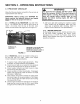
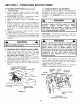
SECTION 3 - OPERATING INSTRUCTIONS 3.2 STOPPING CHOKE CONTROL KNOB IMPORTANT: Pulling backward on both Traction Controls back past Neutral position will cause the machine to back up. 1. Pull back on both Traction Controls simultaneously towards handle bar. Manually engage the Neutral Latch Lever. See Figure 3.2. LEFT HAND TRACTION CONTROL RIGHT HAND TRACTION CONTROL / FUEL TANK & HANDLE BRACKET PULLOUT TO CHOKE POSITION OUTLINE OF REAR WHEEL (Left Side Shown) FIGURE 3.
SECTION 3 - OPERATING INSTRUCTIONS WARNING WARNING The SNAPPER Pro Hydro Mowers have a Transport Speed, which allows the machine to travel forward at a speed of 6 MPH - it is NOT to be used while walking! Use the Transport Speed ONLY when the machine is equipped with a Riding Sulky! DO NOT make sharp turns at high speed! The machine has "zero-turn" capability; DO NOT use "zero-turn" at high speed.
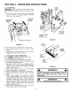
SECTION 3 - OPERATING INSTRUCTIONS 3.7 3.5 MOWER OPERATION (Continued from Previous Page) 5. While holding both Traction Controls in the neutral position, release Neutral Latch Lever by pulling controls slightly backwards. 6. Simultaneously (and slowly), release both Traction Controls. Machine will begin to move forward. 7. Adjust Speed Control Lever to a comfortable travel speed. 8. Proceed to go forward while allowing machine to travel in a straight line.
SECTION 3 - OPERATING 3.7 HANDLE HEIGHT INSTRUCTIONS ADJUSTMENT STEP 7: Adjust swivel (Clockwise or CounterClockwise) until the pin on the swivel aligns perfectly with the hole in the traction control arm. The traction control lever must be held in the Neutral Latch position when making this adjustment. Complete this adjustment for both left and right swivels. Carefully reattach and secure swivels to control arms. Tighten swivel jam nuts.
SECTION 3 - OPERATING 3.8 CUTTING HEIGHT INSTRUCTIONS ADJUSTMENT (Fixed Decks) The Mower has three methods of adjusting cutting height listed as follows: 1. Moving position of BLADE on cutter spindle shaft. 2. Moving position of CASTER WHEEL on support. 3. Moving position of MOWER DECK on power unit. _- / SLOT _ SPACERS WARNING DO NOT attempt any maintenance, adjustments or service with the engine running. Stop engine. Stop blades. Latch Traction Controls in neutral.
SECTION 3 - OPERATING 3.11 ADJUSTING INSTRUCTIONS FIXED DECK ATTACHMENT SPACERS The Mower Deck has four different positions for attaching it to the power unit. The lowest setting provides a cutting height range from 1 1/2" to 2 1t2", the middle low cut from 2 1/4" to 3 1/4", the middle high cut from 3" to 4", and the highest cut from 3 3/4" to 4 3/4". Make sure the Spacers on the Caster Wheels are moved UP or DOWN as shown below to correspond with the bolt positions to keep the Mower Deck level.
SECTION 4 - ENGINE TROUBLESHOOTING SYMPTOM PROBLEM SOLUTION PAGE Engine does not start.. Key OFF. Fuel Tank empty. Fuel Shut-Off Closed. Engine Throttle Control not at FAST (Rabbit) position. Choke NOT closed. Spark Plug Wire loose or disconnected. Blade Clutch Switch in ON position. Spark Plug bad. Dirty Air Fitter. Traction Controts not Latched in Neutral. Turn Key to Run. Fill Fuel Tank. Open Fuel Shut-Off. Put Engine Throttle Control to FAST (Rabbit) position.
SECTION 4 - SERVICE & LUBRICATION TRACTION Lubricate each with 1-2 shots of grease every 25 hours of operation. INFORMATION LINKAGES Before each mowing period, coat all wear points, hinge points and sliding parts with medium duty oil. INTERLOCK SWITCHES Inspectswitches ofoperation. IN-LINE FUEL FILTER (Not Illustrated) Replace every 100 ............................................. Change Oil Filter after first 5 hours of operation.
SECTION 4 - SERVICE & LUBRICATION HOURS BREAK-IN 8 HOURS (Daily) 40 HOURS (Weekly) 200 HOURS (Monthly) PROCEDURE INFORMATION COMMENTS Check all fasteners for proper tightness Change Engine Oil and Filter at 5 hours .............................. See engine manual Change Hydraulic Oil and Filter at 25 hours ........................ Use SAE 10W-30. Reservoir capacity 1 Gal. Check/Change Engine Oil ...................................................
SECTION 4 - SERVICE 2. Before removing parts from the Hydraulic System, check to make sure another part of the machine is not causing the problem. Look for: A. Loose Drive Belt. WARNING Once blades are disengaged, they should come to a complete stop in 7 seconds or less. If the blades continue to rotate after 7 seconds, the electric clutch must be checked. Replacement of electric clutch may be necessary. Return machine to dealer for replacement.
SECTION 4 - SERVICE 4.2.3. HYDRAULIC PUMP BELT REMOVAL (Continued) 2. Loosen Nut on Belt Guide at rear of Engine Pulley and remove Cutter Deck Belt from Engine Pulley. 3. Remove Hydraulic Pump Belt. 4.2.4. HYDRAULIC PUMP BELT INSTALLATION 1. STOP ENGINE! Place Hydraulic Belt on Engine and Pump Pulleys. 2. Attach Idler Spring to Bolt and reattach Nut to Bolt. 3. Place Cutter Deck Belt on Engine Pulley. 4.2.5. REPLACEMENT PARTS To retain the quality of your Machine, use genuine SNAPPER replacement parts only.
SECTION 4 - SERVICE 4.4 TRACTION CONTROL NEUTRAL 9. Wheel rotation will be stopped by adjusting the eccentric on the pump arms on the right and left pumps. Turning the eccentric slightly clockwise or counter-clockwise will synchronize the pump and traction controls for Neutral. See Figure 3.11. To turn the eccentric, first loosen the bolt in the pump control arm and the nut and bolt fastening the eccentric to the pump control arm. With traction controls latched in Neutral, start engine.
SECTION 5 - MOWER ATTACHMENT 5.1 CUTTER DECK BELT REMOVAL SERVICE & ELECTRIC RIGHT INSTALLATION HAND 5.1.1. 36" CUTTING DECK BELT REMOVAL 1. Move Mower onto a smooth, level surface. Turn Ignition Key to STOP position, remove Key, disconnect Spark Plug Wire and secure Wire away from Spark Plug. 2. Remove Mower deck belt cover. 3. Remove Idler Tension Spring and swing Idler away from belt. 4. Remove old belt from Spindle Pulleys and Electric Clutch Pulley. See Figure 5.1.
SECTION 5 - MOWER ATTACHMENT 5.1.5. SPINDLE TO SPINDLE DECK BELT INSTALLATION - 48", 52", & 61" CUTTING DECKS 1. Route new belt for 48" cutting deck, 52" cutting deck, and 61" cutting decks, onto bottom qroove of center Spindle Pulley and left hand Spindle Pulley. See Figure 5.3. 2, Install cutting deck belt according to CUTTING DECK BELT INSTALLATION. 5.2 CUTTING BLADE SERVICE 4. Refer to the STANDARD REPLACEMENT BLADES chart above for correct SNAPPER replacement Blades. 5.
SECTION 5 - MOWER ATTACHMENT 5.3 MOWER SPINDLES (Field Serviceable Spindles) BEARING REPLACEMENT In the event that a spindle bearing requires replacement, the SNAPPER Field Serviceable Spindles have been designed so that no special tools or presses are required. 1. Remove belt. Loosen blade nut and remove. Allow blade bolt, washer, blade and four spacers to drop down out of the spindle housing. See Figure 5.7. 5. Thoroughly clean all parts removing contaminated grease. 6. Install new bottom bearing first.
SECTION 6 - BATTERY SERVICE & TESTING 4. WARNING Shield the positive terminal with terminal cover located on battery harness. This prevents metal from touching the positive terminal, which could cause sparks. Cables must be connected to battery terminals in the proper position. RED (Positive) cable must go to the ( + ) terminal. BLACK (Negative) cable must go to the ( - ) terminal. 6.1 1. 2. 3. 4. 6.2 1. 2, 3. 6.3 BATTERY 5. 6. WARNING REMOVAL Remove battery retainer.
SECTION 6 - BATTERY SERVICE & TESTING 6,5 NEW BATTERY PREPARATION 1. Remove battery from carton. 2. Place battery in a well ventilated area on a level nonconcrete surface. 3. Remove battery cell caps. Fill cells as required with electrolyte (purchased separately) to proper level. Fill to 3/16" above ceil plates. Filling battery with electrolyte wilI bring the battery to 80% charged state. 4.
2 YEAR LIMITED WARRANTY For two (2) years from purchase date for the original purchaser's use, SNAPPER, through any authorized SNAPPER dealer will replace, free of charge (except for taxes where applicable), any part or parts found upon examination by the factory at McDonough, Georgia, to be defective in material or workmanship or both.
PRIMARY MAINTENANCE an illustration of how dirt can dama & how naintenance can protect it! Snapper uses the best available engines and components In their products In order to _= provide long, satisfactory service. However, proper • = care Is essential In "" prolonging engine life.
PRIMARY MAINTENANCE that dirt will quickly ruin an engine, manufacturers equip their englnse with extremely efficient air cleaners to filter out the harmful dirt, gulp about 12,000, gallons of air for every gallon of f= used. Because of its working environment, the air available to your Snapper engine Is " heavily saturated with airborne dirt particles. As the dirt particles are stopped, they build up and begin to clog the outside of the filter.
PRIMARY Generally, wash foam-type filters In a dlshwashlng detergent and water solution. Rinse and wring dry, then saturate with oll and squeeze out excess. Failure to re-oil this type _ter will ruin the engine. Clean paper elements by tapplng MAINTENANCE Air Is also needed to keep your engine coot. Dirt, dust & debris build up to restrict and clog cooling air Intake screens and fins. Clean screens and fins at frequent Intervals.
PRIMARY MAINTENANCE On 2-cycle engines, lubrication must be provided by an exact mixture of gasoline and 2-cycle sir-cooled engine oil A 2-cycle engine that Is mistakenly run on strelght gasoline will be reined in less than 5 mlnutasl If you keep straight gasoline In addition to pre-mlxed 2-cycle engine fuel, be sure the containers are clearly marked to avoid mix-up.
SERVICE NOTES 3O
SERVICE NOTES 31
Safety Instructions & Operator's Manual for PRO HYDRO MID-SIZE WALK BEHIND MOWERS SERIES 1 IMPORTANT Snapper products are built using engines that meet or exceed all applicable emissions requirements on the date manufactured. The labels on those engines contain very important emissions information and critical safety warnings. Read, Understand, and Follow all warnings and instructions in this manual, the engine manual, and on the machine, engine and attachments.