Safety Instructions and Operator's Manual for PRO GEAR EXPRESS WALK BEHIND MOWERS MID-SIZE SERIES 0 POWER UNIT MODEL SPE1250KW SPE140KW SPE150KH MOWER UNIT MODEL SPE361 SPE481 MODEL t NUMBER P E EXPLANATION 125 MODEL DESIGNATION MODEL TYPE MODEL OPTION S - Snapper Commercial P - Pro Mid Size Model E - Express Model Model ENGINE HORSE POWER CUTTING DECK WIDTH 125- 12.5 Engine HP 361 - 36" Cutting Deck 140150- 14.0 Engine HP 15.
IMPORTANT SAFETY INSTRUCTIONS WARNING: This powerful cutting machine is capable of amputating hands and feet and can throw objects that can cause injury and damage! Failure to comply with the following SAFETY instructions could result in serious injury or death to the operator or other persons. The owner of the machine must understand these instructions and must allow only persons who understand these instructions to operate machine.
A IMPORTANT SAFETY INSTRUCTIONS A PREPARATION OPERATION (Continued From Previous Page) 11. Protect yourself when mowing and wear appropriate clothing including safety glasses, long pants, ear protection, hardhat and substantial footwear with good traction. Long hair, loose clothing or jewelry may get tangled in moving parts. 12. Know how to STOP blades and engine quickly in preparation for emergencies. 13. Use extra care when loading or unloading the machine into a trailer or truck. 14.
A IMPORTANT SAFETY INSTRUCTIONS MAINTENANCE (Continued From Previous Page) 7. Disconnect battery before performing maintenance or service. Cranking engine could cause injury. Disconnect negative (black) cable from battery first and positive (red) last. Reconnect positive first and negative last. Charge battery in an open well ventilated area, free from spark and flames. Unplug charger before connecting or disconnecting from battery. Wear protective clothing and insulated gloves. 8.
TABLE OF CONTENTS IMPORTANT SAFETY INSTRUCTIONS ................................................................................... 2-4 TABLE OF CONTENTS ................................................................................................................ 5 SECTION 1 - FAMILIARIZATION ................................................................................................. 6 SECTION 2 - SAFETY MESSAGES&SYMBOLS ...................................................................
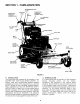
SECTION 1 - FAMILIARIZATION TRANSMISSION LEVER TRACTION OPERATOR'S PRESENCE CONTROL (OPC) LOCK KEY SWITCH SHIFT OPERATOR'S PRESENCE CONTROL (OPC) LH. \ TRACTION LEVER SPEED CONTROL R.H. TRACTION LEVER STARTER ROPE CAP AIR FILTER BELT COVER MUFFLER COVER RETAINING KNOBS DECK COVER DECK (36"SHOWN) 41D ... DISCHARGE DEFLECTOR CASTER WHEEL ASSEMBLY DECK HEIGHT ADJUSTMENTSPACERS FRONT TIRES FIGURE 1.1 1.1 INTRODUCTION 1.
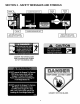
SECTION 2 - SAFETY MESSAGES AND SYMBOLS I i CHOKE I i BLADES ENGAGED"ON" BLADES DISENGAGED"OFF" [E"G'NEI IE"°'NE ] "STOP ....
SECTION 2 - SAFETY MESSAGES AND SYMBOLS IMPORTANT SAFETY AND OPERATING INSTRUCTIONS 8
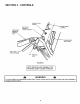
SECTION 2 - CONTROLS BLADE CLUTCH SWITCH OPERATOR'S PRESENCE CONTROL ENGINE SPEED CONTROL KEY SWITCH SHOWN IN "STOP" POSITION (OPC) TRANSMISSION SHIFT LEVER RIGHT HAND TRACTION LEVER TRACTION LOCK FIGURE 2.1 NOTE: TRACTION LOCK SHOWN IN THE TRACTION LEVER "LOCKED" POSITION avoid sudden ITo starting machine and unexpected turning, both Traction Levers must be moved the same way when stopping or _IL WARNING motion.
SECTION 3 - OPERATING 3.1 BEFORE INSTRUCTIONS OPERATING Be thoroughly familiar with all controls and how to use them before operating the machine. Know beforehand how to STOP the Traction Wheel Drives, Mower Blades and Engine in preparation for possible emergencies. 3.2 1. 2, 3. 4. 5. 6. 7. STOPPING When the Operator's Presence Control (OPC) is released, the machine will continue to operate a few feet. DO NOT use WARNING this Operator's Presence Control (OPC) to rout ne y stop the mach he.
SECTION 3 - OPERATING 3.3 PRE-START CHECK INSTRUCTIONS LIST 3. Make the following checks and perform the services as required before each start-up: 1. If required, make cutting height adjustments. Refer to Section "CUTTING HEIGHT ADJUSTMENT". 2, Check tires and add air as needed to bring pressure to 25 psi in front and 12-15 psi in rear tires. 3. Check Guards, Deflector, and Belt Covers to make sure all are in place and secure. 4. Check Condition of Cutter Deck Belt(s).
SECTION 3 - OPERATING 3,4 5. 6. STARTING & OPERATING INSTRUCTIONS - 9. (Continued from previous page) Move Engine Speed Control Lever to the CHOKE position. See Figure 3.5. Turn Key Switch to RUN position. 10. Place Transmission Shift Lever in No. 1 position (first gear). See Figure 3.3. Push Blade Clutch Switch to ON position. See Figure 3.5.
SECTION 3 - OPERATING 3.4 STARTING INSTRUCTIONS & OPERATING WARNING (Continued from previous page) 13. STOPPING MACHINE, Simultaneously squeeze both Traction Levers firmly against the handle and hold. Pull both the right and left Traction Locks rearward with index fingers until both Traction Levers are locked in the Traction Locked position. 14. Pull the Blade Clutch Switch rearward to the OFF DO NOT operate blades in reverse. Stop blades.
SECTION 3 - OPERATING INSTRUCTIONS WARNING Brakes require maintenance. operation before operating Section "ADJUSTMENTS, BRAKES". 3.6 TRACTION 3.6.1 TO LOCK LOCK &l WARNING Inspect for proper machine. Refer to STEERING AND OPERATION Machine should always be in forward motion before I attempting a turn. DO NOT attempt a turn from a[ stopped position. I 3.7 TURNING MOWER 3.7.1. GRADUAL RIGHT & LEFT HAND TURN - 1.
SECTION 3 - OPERATING 3.9 CUTTING HEIGHT INSTRUCTIONS 3.11 ADJUSTMENT ADJUSTING BLADE ON CUTTER SPINDLE (Fixed Decks) Mower has three methods of adjusting cutting height: 1. Moving position of BLADE on cutter spindle shaft. 2. Moving position of CASTER WHEEL on support. 3. Moving position of MOWER DECK on power unit. To change cutting height of Blades, move the Spacers from under the Cutter Housing to above the Cutter Housing Pulley.
SECTION 3 - OPERATING 3.11 INSTRUCTIONS ADJUSTING BLADE ON CUTTER SPINDLE (Continued) SPACERS CUTTER SPACERS HOUSING PULLEY t!l_ _ ON TOP _......--, ._... ,....,,,.,,,,,,....._ CUTTER I r" BLAO l f _1 HOUSING FIGURE 3.15C: MIDDLE HIGH CUT 3" TO 4" BOTTOM SPACERS ON u_ SPACERS FIGURE 3.14 3.12 ADJUSTING FIXED DECK ATTACHMENT The mower deck has four different positions for attaching it to the power unit.
SECTION 4 - TROUBLESHOOTING ENGINE TROUBLESHOOTING SYMPTOM PROBLEM Engine ................... does not ................ stare ...................... ............................... ............................... Key OFF. .............................................................................................. .Turn Key to Run. Fuel Tank empty. .................................................................................. Fill Fuel Tank. Fuel Shut-Off Closed. ..................................
SECTION 4 - TROUBLESHOOTING MOWER TROUBLESHOOTING (Continued) SYMPTOM PROBLEM SOLUTION Mower not ...................................... cutting full ...................................... width. Broken or slipping Blade Belt ....................................... Dull, Damaged or Worn Blades ................................... Replace Belt. Sharpen Blades or Install new Blades Discharge ....................................... Deflector Becomes ........................ Obstructed ..................
SECTION 5 - ADJUSTMENTS 5.1 Pull rearward hard on the Traction Levers. The space used to lock the Traction Locks should not bottom in the slot. Set the Traction Locks into the STEERING/BRAKES If machine is not as responsive as desired when either Traction Lever is squeezed, one or both brakes should be adjusted as follows: 1. 2. 3. Locked position. The Idler Pulleys, Upper and Lower should have completely declutched the belt. Release the Traction Locks and adjust as required.
SECTION 5 - ADJUSTMENTS 5.3 HANDLE HEIGHT The operator handle can comfort as follows: 1. 2. 3. 4. 5. 6. 7. 5.4 be adjusted for operator 1. Loosen the upper carriage bolt and nut on both sides of handlebar. See Figure 5.4. Remove lower carriage bolt and nut on both sides of handlebar. Raise or lower handlebar to desired height. See Figure 5.3. Install the carriage bolt and nut in the lower hole in handlebar and securely tighten nut. See Figure 5.4. Securely tighten the upper carriage bolt and nut.
SECTION 6 - POWER UNIT SERVICE 6,1 REPLACEMENT 6.2,2, TRANSMISSION The Peerless MST 205 Series Transmission requires no routine maintenance. Return machine to an authorized Snapper dealer for service, maintenance or problems. PARTS To retain the quality of your mower, use Genuine SNAPPER Replacement Parts only! Contact your local SNAPPER dealer for parts and service assistance. For the correct part or information for your mower, always mention Model and Serial Number of Power Unit and 6.2,3.
SECTION 7 - MOWER ATTACHMENT 7.1 TRANSMISSION BELT REMOVAL/REPLACEMENT SERVICE Adjust Traction Rod and Brake Rod as necessary. Refer to Section "ADJUSTMENTS STEERING/BRAKES and TRACTION LEVERS/RODS". 4, WARNING TRACTION DO NOT attempt any maintenance, adjustments or service with the engine running. Stop engine. Stop blades. Lock Traction Levers. Remove key. Disconnect spark plug wires from spark plugs and secure wires away from spark plugs. Engine and components are HOT.
SECTION 7 - MOWER ATTACHMENT 7.4 CUTTING BLADE SERVICE SERVICE WARNING Check blades after each use for signs of excessive wear and damage. See Figure 7.4 for blade wear limits. " Blades are extremely sharp and can cause severe injury. Wear heavy leather gloves when handling or working around blades. DO NOT use a blade that is excessively worn or damaged. NEW BLADE" HEAVY END OF BLADE 22 ° TO 28° BLADE _'_t_ WEAR LIMIT _._.
SECTION 7 - MOWER ATTACHMENT 7.5 MOWER SPINDLES (Field Serviceable Spindles) BEARING REPLACEMENT In the event that a spindle bearing requires replacement, the SNAPPER Field Serviceable Spindles have been designed so that no special tools or presses are required. 1. Remove belt. Loosen blade nut and remove. Allow blade bolt, washer, blade and four spacers to drop down out of the spindle housing. See Figure 7.7. 5. 6. 7. 0 / REMOVE BELT FIGURE 7.
ELECTRICAL OPC SWITCH (PISTOL GRIP MODELS ONLY) KEY WITH COVER BLADE CLUTCH SWITCH KEYSWITCH...-----_ OPC SWITCH (PISTOL GRIP MODELS) 15 AMP FUSE MAIN HARNESS TO TRANSMISSION SWITCH KAWASAKI ENGINE ONLY i__ KAWASAKI MODULE PIGTAIL TO ELECTRIC KAWASAKI CAPACITOR TO MAIN HARNESS GROUND TO ENGINE NOTE:THIS TERMINAL HAS A LOCK-OUT TO ENGINETERMINAL BARB WHICHMUSTSLIDEINTOTHECONNECTOR NOTCH. FIGURE 7.
ELECTRICAL ELECTRIC BLACK CLUTCH [_ BLUEs 15A FUSE _ ENGINE GREEN YELLOW GREEN IGNITION RED RED BLACK _ IISEE NOTEI _ OPC RED WHITE ]' _ R,H. _ YELLOW OPC L,H. YELLOW4 TRANSMISSION BLACK WIRING SCHEMATIC FOR PISTOL GRIP HANDLE FIGURE & ELECTRIC BLADE BRAKE CLUTCH 7,10 TRANS SWITCH (SEE NOTE) RED (16 GA) ;REEN (14 GA) D% RED{t_ 0.*} II_.,U E (_40A) YELLOW (16 ENGINE TE(IG R.H. OPC L,H.
2 YEAR LIMITED WARRANTY For two (2) years from purchase date for the original purchaser's use, SNAPPER, through any authorized SNAPPER dealer will replace, free of charge (except for taxes where applicable), any part or parts found upon examination by the factory at McDonough, Georgia, to be defective in material or workmanship or both.
PRIMARY MAINTENANCE an illustration of how dirt can dama & how naintenance can protect it! Snapper uses the best available engines and components In their products In order to _= provide long, satisfactory service. However, proper • = care Is essential In "" prolonging engine life.
PRIMARY MAINTENANCE that dirt will quickly ruin an engine, manufacturers equip their englnse with extremely efficient air cleaners to filter out the harmful dirt, gulp about 12,000, gallons of air for every gallon of f= used. Because of Its working environment, the air available to your Snapper engine Is " heavily saturated with airborne dirt particles. As the dirt pertlclse are stopped, they build up and begin to clog the outside of the filter.
PRIMARY MAINTENANCE Generally, wash foam-type filters In a dlshwashlng detergent and water solution. Rinse and wring dry, then saturate with oll and squeeze out excess. Failure to re-oil this type _ter will ruin the engine. Clean paper elements by tapplng Air Is also needed to keep your engine coot. Dirt, dust & debris build up to restrict and clog cooling air Intake screens and fins. Clean screens and fins at frequent Intervals.
PRIMARY MAINTENANCE On 2-cyele engines, lubrication must be provided by an exact mixture of gasoline and 2-cycle air-cooled engine oil. A 2-cycle engine that Is mistakenly run on strelght gasoline will be ruined in less than 5 mlnutosl If you keep straight gasoline In addition to pre-mlxed 2-cycle engine fuel, be sure the containers are clearly marked to avoid mix-up.
NOTES 32
NOTES 33
Safety Instructions and Operator's Manual for PRO GEAR EXPRESS MID-SIZE WALK BEHIND MOWERS SERIES 0 IMPORTANT Snapper products are built using engines that meet or exceed all applicable emissions requirements on the date manufactured. The labels on those engines contain very important emissions information and critical safety warnings. Read, Understand, and Follow all warnings and instructions in this manual, the engine manual, and on the machine, engine and attachments.