Safety Instructions & Operator's Manual for 21" STEEL DECK WALK MOWERS "M" MODEL SERIES 17 MODELS PUSH MODEL PROPELLED MODEL MR216017B MR216017BV WMR216017B WMR216017B V MR216517B MRP216017B MRP216017BV WMRP216017B MRP216517B MODEL NUMBER EXPLANATION IMI MODEL DESIGNATION SELF-PROPELLED CUTTING WIDTH 1 M - Model Designation P - Self Propelled Model W - Model Designation R - Recycling Model 21 - 21" Cutting Width 60 - 6.0 HP 66 - 6.6 HP (En.
IMPORTANT SAFETY INSTRUCTIONS WARNING: This powerful cutting machine is capable of amputating hands and feet and can throw objects that can cause injury and damage! Failure to comply with the following SAFETY instructions could result in serious injury or death to the operator or other persons. The owner of the machine must understand these instructions and must allow only persons who understand these instructions to operate machine.
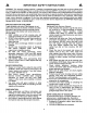
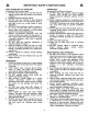
IMPORTANT SAFE HANDLING SAFETY INSTRUCTIONS OF GASOLINE (Continued From Previous Page) 3. DO NOT remove fuel cap or add fuel with the engine running. Allow the engine to cool before refueling. 4. DO NOT refuel the machine indoors. 5. DO NOT store the machine or fuel container inside where there is an open flame, spark or pilot light such as on a water heater or other appliances. 6. DO NOT fill fuel containers inside a vehicle or on a truck or trailer bed with a plastic liner.
IMPORTANT MAINTENANCE SAFETY INSTRUCTIONS AND STORAGE (Continued From Previous Page) 9. Mower blades are sharp and can cut. Wrap the blades or wear heavy leather gloves and use CAUTION when handling them. 10. DO NOT test for spark by grounding spark plug next to spark plug hole; spark plug could ignite gas exiting engine. 11. Have machine serviced by an authorized SNAPPER dealer at least once a year and have the dealer install any new safety devices. 12.
TABLE OF CONTENTS IMPORTANT SAFETY INSTRUCTIONS .............................................. TABLE OF CONTENTS ............................................................................ SECTION 1 - FAMILIARIZATION .............................................................. SECTION 2 - OPERATING INSTRUCTIONS ....................................... 2 -4 5 6 7-11 Pre-start Checklist ......................................................................................................
Section 1 - FAMILIARIZATION =................................................................................................ i GROUND j SPEED WHEEL DRIVE CONTROL HANDLE FAST_ i i \ i CONTROL START ROPE HANDLE ow CONTROL KNOB MID-HANDLE BRIGGS & STRATTON ENGINE PRIMER BULB LOCATED AT FRONT OF ENGINE ADJUSTMENT LEVER TECUMSEH ENGINE PRIMER BULB LOCATED ON RIGHT SIDE OF ENGINE LOWER HANDLE FUEL FILLER CAP MUFFLER REAR WHEEL MOWER DECK ENGINE mR FILTER COVER RECYCLING DECK COVER FRONT WH
Section 2 - OPERATING 2.1 INSTRUCTIONS PRE-START CHECK LIST Make the following checks and perform the service required before each start-up. 2.1.1. Check guards, deflectors, grass bag, adapter and covers to make sure all are in place and securely tightened. 2.1.2. Check blade control and wheel drive control to insure they work freely. See Figure 2.1. 2.1.6. Clean exterior surfaces of cutting deck and engine of any accumulation of spilled fuel, dirt, grass, oil, etc.
Section 2 - OPERATING 2.2 INSTRUCTIONS STARTING & OPERATION HIGHER WARNING ...... LOWER HANDLE Stop engine and mower blade by releasing the blade control before adjusting ground speed. 2.2.2. PROPELLING MOWER (Self Propelled Model Only) 1. Stop engine and mower blade by releasing the blade control before adjusting ground speed. Move ground speed control to the desired speed position. See Figure 2.4. 2. Start engine. Refer to Section "Starting Operation". 3.
Section 2 - OPERATING INSTRUCTIONS WARNING DO NOT attempt any maintenance, adjustments or service with engine and blade running. STOP engine and blade. Disconnect spark plug wire and secure away from spark plug. Engine and components are HOT. Avoid serious burns, allow sufficient time for all components to cool. INSTALLATION of RECYCLING PLUG (Optional Accessory on Some Models) STEP 1: Once adapter has been installed, recycling may be desired. Insert recycling plug completely and securely into adapter.
Section 2 - OPERATING INSTRUCTIONS B. Position grass bag between handles. See Figure 2.12. Install grass bag by sliding connector over flange of adapter. Attach grass bag hooks over middle handle cross bar. See Figure 2.13. WARNING DO NOT attempt any maintenance, adjustments or service with engine and blade running. STOP engine and blade. Disconnect spark plug wire and secure away from spark plug. Engine and components are HOT. Avoid serious burns, allow sufficient time for all components to cool. 2.
Section 2 - OPERATING INSTRUCTIONS WARNING INSTALL DISCHARGE DEFLECTOR DO NOT attempt any maintenance, adjustments or service with engine and blade running. STOP engine and blade. Disconnect spark plug wire and secure away from spark plug. Engine and components are HOT. Avoid serious burns, allow sufficient time for all components to cool. 2.10 INSTALLATION SLIDE DEFLECTOR SLOT of DISCHARGE DEFLECTOR (Optional Accessory On Some Models) Install discharge deflector if discharging is desired.
Section 3 - MAINTENANCE 3.1 INTRODUCTION To retain the quality of the mower, use genuine SNAPPER replacement parts only. Contact a local SNAPPER dealer for parts and service assistance. For the correct part or information for a particular mower, always mention model and serial number. 3.2 SERVICE - AFTER FIRST 5 HOURS 3.2.1. CHANGE ENGINE OIL 3.2.2. CHECK GREASE LEVEL IN TRANSMISSION 1. Remove transmission fill plug. See Figure 3.2. 2.
Section 3 - MAINTENANCE 3.2.2. CHECK GREASE LEVEL IN TRANSMISSION 3.2.4. CHECK ENGINE DRIVE BELT 1. Visually check engine drive belt for cracking, fraying, severed or belt strands exposed. If worn or damaged, replace belt before operating mower. NOTE: Do not spill grease or oil on surface of drive disc. See Figure 3.3. 3. Reinstall transmission plug. 4. Check grease level after each operation. 25 hours 3.2.5. CHECK TRANSMISSION POLY-V BELT 1.
Section 4 - ADJUSTMENTS _IL WARNING & REPAIR 2. Replace the blade if it is badly chipped, bent, noticeably out of balance or has cracks or notch in either tip. See Figure 4.1 & 4.2. Replace with new blade. _, DO NOT attempt any maintenance, adjustments or service with engine and blade running. STOP engine and blade. Disconnect spark plug wire and secure away from spark plug. Engine and components are HOT. Avoid serious burns, allow sufficient time for all components to cool.
Section 4 - ADJUSTMENTS & REPAIR WARNING DO NOT attempt any maintenance, adjustments or service with engine and blade running. STOP engine and blade. Disconnect spark plug wire and secure away from spark plug. Engine and components are HOT. Avoid serious burns, allow sufficient time for all components to cool. _.LUTCH 1/16" TO 1/8" CLEARANCE UPPER SPRING HOOKiiiii SPRING .ii 4. Sharpen blade on a grinding wheel at an angle of 22 to 28 degrees. DO NOT sharpen blade beyond original cutting edge.
Section 4 - ADJUSTMENTS & REPAIR WARNING DO NOT attempt any maintenance, adjustments or service with engine and blade running. STOP engine and blade. Disconnect spark plug wire and secure away from spark plug. Engine and components are HOT. Avoid serious burns, allow sufficient time for all components to cool. 4.3 DRIVEN AND DRIVE DISC SERVICE If the mower does not propel itself properly, See Figure 4.6. Check for the following problems: DRIVEN DISC & RUBBER RING iiiDRIVE 8PRINGi, ....................
Section 4 - ADJUSTMENTS & REPAIR WARNING DO NOT attempt any maintenance, adjustments or service with engine and blade running. STOP engine and blade. Disconnect spark plug wire and secure away from spark plug. Engine and components are HOT. Avoid serious burns, allow sufficient time for all components to cool. 4.3.3. SLIDE DRIVEN DISC TOWARD OUTSIDE EDGE 1/8" MEASUREMENT OUTSIDE EDGE OF 91- DRIVE DISC TO DRIVE DRIVEN DISC ADJUSTMENT (Continued From Previous Page) 2.
Section 4 - ADJUSTMENTS & REPAIR 4.3.5. Replacing Bearing In Driven Disc Assembly IMPORTANT: The bearing, on these "M" series machines, is staked into the thrust plate. The bearing will have to be driven out with a mallet and a large punch. A new bearing with four retaining screws will have to be purchased to replace existing bearing. If the driven disc bearing requires replacement, remove the driven disc assembly and replace bearing as follows: 1.
Section 4 - ADJUSTMENTS & REPAIR 4.4 WARNING DO NOT attempt any maintenance, adjustments or service with engine and blade running. STOP engine and blade. Disconnect spark plug wire and secure away from spark plug. Engine and components are HOT. Avoid serious burns, allow sufficient time for all components to cool. 4.3.6. Replacement Of Bearing On Pulley End Of Hex Shaft To replace the bearing on the pulley end of the hex shaft, proceed as follows: 1.
Section 4 - ADJUSTMENTS & REPAIR 9. Loop the belt around the pulley on the bottom of the drive disc. 10. Reinstall drive disc and retaining hardware. IMPORTANT: 1) The square shoulder of the drive disc bolt must fit into the square hole of the bushing. 2) The square end of bushing must fit into the bracket slot. 11. Reinstall belt cover and tighten bolts securely. 12. Reinstall blade hub and cutter blade. Recommended torque for blade cap screw is 40 ft. Ibs.
TROUBLESHOOTING PROBLEM PROBABLE CAUSE CORRECTIVE ACTION Engine Will Not Start 1. Fuel tank empty. 1. Fill fuel tank with fresh fuel. Using Recoil Starter 2. Engine needs choking or priming. 2.Choke/Prime. Check Engine Manual for Instructions. 3. Place spark plug wire onto spark plug. 3. Spark plug wire disconnected.
SERVICE SCHEDULE ITEM SERVICE PERFORMED Engine Oil Air Pre-Cleaner REF.
3 YEAR LIMITED WARRANTY For three (3) years from purchase date for the original purchaser's residential, non-commercial use, SNAPPER, through any authorized SNAPPER dealer will replace, free of charge (except for taxes where applicable), any part or parts found upon examination by the factory at McDonough, Georgia, to be defective in material or workmanship or both.
SNAPPER PRODUCT IMPORTANT: KEEP THIS INFORMATION (Complete Model REGISTRATION the following FORM FOR YOUR PERSONAL information on your Snapper RECORDS purchase) Number Serial Number Date of Purchase Retailer Retailer's Phone It is very warranty Snapper Number important coverage. Please at P.O. Box 1379, Or you may register You can contact Service that register your mail your product McDonough, purchase registration Georgia Snapper to ensure card to: 30253.
PRIMARY MAINTENANCE I an illustration of how dirt can damage your engine & how reasonable can protect it! )er uses the best availngines and components in their products in order to provide long, satisfactory service. However, proper • care is essential In _'" prolonging engine life.
PRIMARY MAINTENANCE \ _g that dirt will quickly ruin an engine, manufacturers equip their engines with extremely efficient air cleaners to the harmful dirt. The engine must gulp about 12 gallons of air for every gallon of fuel its working ment, the air avail to your Snapper eng heavily saturated with airborne dirt particles. As the dirt particles are stopped, they build up and begin to clog the outside of the filter.
PRIMARY MAINTENANCE • i Generally, wash foam-type filters In a dlshwashlng detergent and water solution. Rinse and wring dry, then saturate with oil and squeeze out excess. Failure to re-oil this type filter will ruin the engine. Air Is also needed to keep your engine cool. Dirt, dust & debris build up to restrict and clog cooling air Intake screens and fins. Clean screens and fins at frequent Intervals.
PRIMARY MAINTENANCE On 2-cycle engines, lubrication must be provided by an exact mixture of gasoline and 2-cycle air-cooled engine oil A 2-cycle engine that Is mistakenly run on straight gasoline will be ruined in less than 5 minutasl If you keep straight gasoline In addition to pre-mixed 2-cycle engine fuel, be sure the containers are clearly marked to avoid mix-up.
NOTES 29
NOTES 30
NOTES 31
Safety Instructions & Operator's Manual for 21" STEEL DECK WALK BEHIND MOWERS "M" MODEL SERIES 17 IMPORTANT Snapper products are built using engines that meet or exceed all applicable emissions requirements on the date manufactured. The labels on those engines contain very important emissions information and critical safety warnings. Read, Understand, and Follow all warnings and instructions in this manual, the engine manual, and on the machine, engine and attachments.