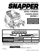
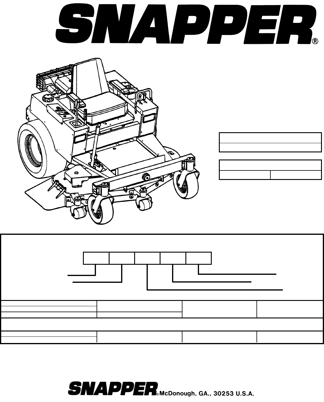
Safety Instructions & Operator’s Manual for MID MOUNT Z-RIDER ZERO TURNING HYDRO DRIVE SERIES 1 POWER UNIT MODELS ZM2501KH MOWER UNIT MODELS ZM5200M ZM6100M MODEL NUMBER EXPLANATION Z M 25 01 KH DRIVE SYSTEM TYPE MOWER ORIENTATION ENGINE TYPE SERIES DESIGNATION ENGINE HP POWER UNIT Z – Zero Turning – Hydro Drive M – Mid Mount Mower 25 – Engine Horse Power Z – Zero Turning – Hydro Drive M – Mid Mount Mower 52 – Mower Cutting Width 61 – Mower Cutting Width 01 – Series Designation KH – Kohler
IMPORTANT SAFETY INSTRUCTIONS WARNING: This powerful cutting machine is capable of amputating hands and feet and can throw objects that can cause injury and damage! Failure to comply with the following SAFETY instructions could result in serious injury or death to the operator or other persons. The owner of the machine must understand these instructions and must allow only persons who understand these instructions to operate machine.
IMPORTANT SAFETY INSTRUCTIONS PREPARATION OPERATION (Continued From Previous Page) 5. Practice operation of machine with BLADES OFF to learn controls and develop skills. 6. Check the area to be mowed and remove all objects such as toys, wire, rocks, limbs and other objects that could cause injury if thrown by blades or interfere with mowing. 7. Keep people and pets out of mowing area. Immediately, STOP blades, STOP engine, and STOP machine if anyone enters the area. 8.
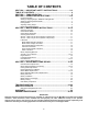
TABLE OF CONTENTS SECTION 1 - IMPORTANT SAFETY INSTRUCTIONS.......................... 2-3 TABLE OF CONTENTS ............................................................................ 4 SECTION 1 – FAMILIARIZATION............................................................. 5 SECTION 2 - OPERATING INSTRUCTIONS......................................... 6-9 Pre-start Checklist .................................................................................................
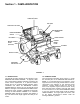
Section 1 - FAMILIARIZATION OPERATOR’S SEAT FUEL TANK AUXILLARY FUEL TANK ENGINE SPEED CONTROL BLADE ENGAGEMENT SWITCH KEY SWITCH CHOKE CONTROL PARKING BRAKE LEVER MOTION CONTROL LEVER (JOYSTICK) FOOTREST DECK LIFT LEVER DISCHARGE DEFLECTOR FIGURE 1.1 1.1 INTRODUCTION This manual has been prepared for the operator’s of the SNAPPER MID MOUNT Z-RIDER.
Section 2 - OPERATING INSTRUCTIONS IMPORTANT: This machine is equipped with hydrostatic drive. The forward and rearward movement of the mower is controlled by a joystick lever. Joystick operations should be performed only from the operator’s position in the seat. A small movement of the joystick can cause the machine to move instantly. Move joystick very carefully and slowly. 2.1 PRE-START CHECK LIST Make the following checks and perform the service required before each start-up. 2.1.1.
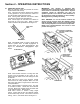
Section 2 - OPERATING INSTRUCTIONS 2.2 STARTING & STOPPING – ENGINE, BLADES, PARKING BRAKE This machine is equipped with dual hydrostatic wheel drive transmissions. Each transmission is controlled by a single motion control lever or joystick. This single control lever (joystick) controls the direction of motion, Forward and Reverse, and the speed of motion. Move the joystick forward to propel the machine forward. Move the control rearward to propel the machine in reverse.
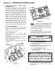
Section 2 - OPERATING INSTRUCTIONS 2.2.5. PARKING BRAKE 1. Engage parking brake by pulling the parking brake lever back to the engaged position. NOTE: Motion control lever must be in the Neutral position to engage brake. See Figure. 2.6. NOTE: Engaging the parking brake locks the motion control lever (joystick) in the neutral position. 2. Release parking brake by pushing parking brake lever forward to the released position. See Figure 2.7. WARNING DO NOT park the machine on slopes.
Section 2 - OPERATING INSTRUCTIONS 2.3 CUTTING HEIGHT ADJUSTMENT 1. Adjust cutting height as desired to any position, using deck lift lever. See Figure 2.8. NOTE: The engine does not have to be running to adjust cutting height. WARNING DO NOT make turns at high speed. Slow machine motion. Move motion control lever gently and with caution. DO NOT make sudden changes in speed or direction. 2.4.2. STOPPING MACHINE 1. Return motion control lever (joystick) to neutral.
Section 3 - MAINTENANCE d. Fill engine crankcase with new oil. Refer to your engine owner’s manual for oil specifications. e. Change oil filter at every oil change. Refer to your engine owner’s manual for service instructions. 3.1 INTRODUCTION To retain the quality of the SNAPPER mower, use genuine SNAPPER replacement parts only. Contact a local SNAPPER dealer for parts and service assistance. For the correct part or information for a particular SNAPPER mower, always mention the model and serial number.
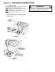
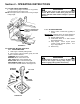
Section 3 - MAINTENANCE 3.2.3. CHECK MOWER DRIVE BELT 1. Foot Rest Removal a. Lower deck to lowest setting. b. Remove foot rest. See Figure 3.3. c. Removal of foot rest will allow access to deck belt. LIFT FOOT REST UP AND OFF POWER UNIT FRAME TO GAIN ACCESS TO MOWER BELT c. Raise mower deck to its highest setting. It may be necessary to raise mower deck higher using a hydraulic floor jack. Secure machine with safety blocks. d.
Section 3 - MAINTENANCE 3.3.3. RIDING MOWER - LUBRICATION 1. Front Wheel Bearings Lubricate with Kendall NLGI No. 2 lithium grease or equivalent, from a grease gun. See Figure 3.5. 3. Power Transfer Shaft Lubricate power transfer shaft with Kendall NLGI No. 2 lithium grease or equivalent, from a grease gun. See Figure 3.7. VIEW IS SHOWN WITH PARTS REMOVED FOR CLEAR VIEW OF SHAFT LUBRICATE BEARINGS LUBRICATE POWER TRANSFER SHAFT FRONT WHEEL FIGURE 3.5 2.
Section 3 - MAINTENANCE 3.5 ANNUALLY (END OF EACH SEASON) (Continued from previous Page) 3.5.2. FUEL FILTER Service fuel filter as instructed below. Turn key to “OFF” position. Engine MUST be stopped and MUST be cold before removing filter. Clamp fuel line to prevent fuel spillage or perform filter change when fuel tank and fuel line are empty. POSITION DECK LIFT LEVER IN HIGHEST CUTTING POSITION. PLACE WOODEN BLOCKS UNDER FRONT AND REAR OF DECK.
Section 3 - MAINTENANCE 3.6 DECK REMOVAL (Continued from previous page) TRANSFER SHAFT 5. Remove shoulder bolts, washers and nuts from rear lift arm. See Figure 3.11. LOCK COLLAR REAR LIFT ARM TAKE OFF SHAFT REAR LINK PLATE SHOULDER BOLT, WASHER & NUT THREADED END FIGURE 3.13 FIGURE 3.11 IMPORTANT: Mower deck is extremely heavy. Be very careful when removing deck from power unit. 6. Disconnect pull bar from front axle by removing clevis pins and cotter pins. See Figure 3.12. 8.
Section 4 - ADJUSTMENTS & REPAIR 4.2 MOWER DECK & COMPONENT ADJUSTMENTS The following mower deck and component adjustments and repairs can be made by the owner. However, if there is difficulty in making these adjustments and repairs, it is recommended that these repairs be made by an authorized SNAPPER dealer. 4.2.1.
Section 4 - ADJUSTMENTS & REPAIR 4.2.1. MOWER DECK ADJUSTMENT (LEVELNESS) (Continued) 6. Loosen the nuts and bolts that secure both front and rear deck support brackets on the high side of deck. Located above each support bracket, on the top part of the power unit frame, are three shim plates. Remove the shim plates on both of the front and rear lift arms and position plates between the support bracket and the frame of the power unit.
Section 4 - ADJUSTMENTS & REPAIR 4.4 ENGINE ADJUSTMENTS & REPAIR Refer to the engine owner’s manual for engine adjustments and/or repairs. WARNING Before attempting any adjustments, maintenance, service, or repairs, stop engine and blade, always remove key from ignition switch, remove spark plug wire(s) and secure wire(s) away from spark plug(s). WARNING Wear heavy leather gloves when handling or working around cutting blades. Blades are extremely sharp and can cause severe injury.
Section 4 - ADJUSTMENTS & REPAIR 4.6 MOWER DRIVE BELT REPLACEMENT Inspect mower drive belt. Replace belt if it shows signs of excessive wear, damage and/or is broken. 4.5.2. BLADE SHARPENING 1. Remove blade. See Figure 4.5. 4.6.1. BELT REMOVAL 1. Remove power unit foot rest. 2. Remove old belt. BLADE 4.6.2. BELT REPLACEMENT 1. Route belt around blade pulleys and idler pulley in same the position as old belt was removed. It may be necessary to use a pry bar to pull idler pulley back to install belt.
Section 4 - ADJUSTMENTS & REPAIR 4. With cell caps removed, connect battery charger to battery terminals. RED to positive (+) terminal and BLACK to negative (-) terminal. 5. Slow charge battery at 1 amp for 10 hours. An alternative fast charge should be no more than 2.5 amps for four hours. 6. If battery will not accept charge or is partially charged after 10 hours of charging at 1 amp, replace with new battery. WARNING Shield the positive terminal with terminal cover located on battery harness.
Section 4 - ADJUSTMENTS & REPAIR Battery Condition Chart State of Charge 100% Charged w/ Sulfate Stop 100% Charged 75% Charged 50% Charged 25% Charged 0% Charged Syringe Hydrometer 1.280 1.265 1.210 1.160 1.120 Less than 1.100 4.7.4. BATTERY TESTING There are two types of battery tests: Unloaded and Loaded. The unloaded test is the procedure that will be discussed. It’s the simplest and most commonly used. An unloaded test is made on a battery without discharging current.
TROUBLESHOOTING PROBLEM PROBABLE CAUSE CORRECTIVE ACTION Starter Will Not Crank 1. Battery dead. 2. Blown fuse. Engine 3. Electrical connections loose or corroded. 4. Defective ignition switch. Engine Will Not Start 1. Blade engagement switch in the “ON” position. 2. Park brake not set. 3. Fuel tank empty. 4. Engine needs choking. 5. Spark plug wire disconnected. 6. Battery weak or dead. 7. Faulty parking brake, blade or ignition switch. Engine Stalls After Running 1. Operator not in seat. 2.
TROUBLESHOOTING PROBLEM Tractor Will Not Move Loss Of Traction Blade(s) Not Cutting Cutting Grass Improperly Poor Grass Discharge PROBABLE CAUSE CORRECTIVE ACTION 1. Joystick in the neutral “N” position. 2. Roll release lever is in “ROLL” position. 3. Low transmission hydraulic oil level. 4. Parking Brake engaged. 5. Traction drive belt requires replacement 1. Place joystick in desired speed position. 2. Move roll release lever to the engaged position. 3. Bring hydraulic oil to proper level. 4.
SERVICE SCHEDULE ITEM SERVICE PERFORMED REF. EACH USE X 5 HRS 25 HRS 50 HRS 100 HRS EACH SEASON Check Oil Level Page 6 Initial Oil Change Page 10 Periodic Oil Change Page 11 Air Pre-Cleaner Clean Sponge Element Air Cleaner Clean or Replace Engine Manual & Page 11. Engine Manual. Spark Plug Replace Engine Manual.
2 YEAR LIMITED WARRANTY For two (2) years from purchase date for the original purchaser's use, SNAPPER, through any authorized SNAPPER dealer will replace, free of charge (except for taxes where applicable), any part or parts found upon examination by the factory at McDonough, Georgia, to be defective in material or workmanship or both.
PRIMARY MAINTENANCE 25
PRIMARY MAINTENANCE 26
PRIMARY MAINTENANCE 27
PRIMARY MAINTENANCE 28
NOTES 29
NOTES 30
NOTES 31
Safety Instructions & Operator’s Manual for MID MOUNT Z-RIDER ZERO TURNING HYDRO DRIVE SERIES 1 IMPORTANT Snapper products are built using engines that meet or exceed all applicable emissions requirements on the date manufactured. The labels on those engines contain very important emissions information and critical safety warnings. Read, Understand, and Follow all warnings and instructions in this manual, the engine manual, and on the machine, engine and attachments.