Owner/Operator Manual Manuel Du Propriétaire/Utilisateur Models 920402 – Sno-Tek 24E 920403 – Sno-Tek 28E ENGLISH FRANÇAIS 04135200 5/10 Printed in USA
TABLE OF CONTENTS SAFETY. . . . . . . . . . . . . . . . . . . . . . . . . . 4 STORAGE . . . . . . . . . . . . . . . . . . . . . . . 28 ASSEMBLY . . . . . . . . . . . . . . . . . . . . . . . 8 SERVICE PARTS . . . . . . . . . . . . . . . . . 28 CONTROLS and FEATURES . . . . . . . . 11 ACCESSORIES. . . . . . . . . . . . . . . . . . . 28 OPERATION . . . . . . . . . . . . . . . . . . . . . 12 TROUBLESHOOTING . . . . . . . . . . . . . 29 MAINTENANCE . . . . . . . . . . . . . . . . . . 17 SPECIFICATIONS .
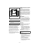
UNAUTHORIZED REPLACEMENT PARTS Serial Number Label Use only Ariens replacement parts. The replacement of any part on this vehicle with anything other than an Ariens authorized replacement part may adversely affect the performance, durability, or safety of this unit and may void the warranty. Ariens disclaims liability for any claims or damages, whether warranty, property damage, personal injury or death arising out of the use of unauthorized replacement parts.
SAFETY PRACTICES AND LAWS WARNING: To avoid injury to hands and feet, always disengage clutches, shut off engine, and wait for all movement to stop before unclogging or working on snow thrower. Hand contact with the rotating impeller is the most common cause of injury associated with snow throwers. Never use your hand to clean out the discharge chute. Keep hands and feet away from auger and impeller. SAFETY ALERTS Look for these symbols to point out important safety precautions.
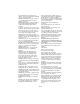
1. WARNING! 3. DANGER! Read Owner/Operator Manual. OL1801 OS2080 Keep people away from unit while operating. Keep children out of work area and under watchful care of a responsible adult. OL4370 Never direct discharge towards persons or property that may be injured or damaged by thrown objects. OL0910 Stop engine, remove key, read manual before making any repairs or adjustments. OL4010 Wear appropriate hearing protection. OL4690 ONLY use clean-out tool to clear blockages. NEVER use your hands.
Keep children and people away. Keep children out of work area and under watchful care of a responsible adult. NEVER allow children to operate or play on or near unit. Be alert and shut off unit if children enter area. DO NOT allow adults to operate unit without proper training. Only trained adults may operate unit. Training includes actual operation. Keep area of operation clear of all toys, pets, and debris. Thrown objects can cause injury. Check for weak spots on docks, ramps or floors.
Before cleaning, removing clogs or making any inspections, repairs, etc.: disengage clutch(es), stop unit and engine, remove key, allow moving parts to stop. Allow hot parts to cool. Run unit a few minutes after clearing snow to prevent freeze-up of attachment. Disengage attachment when not in use. Disengage all clutches before starting engine. Adjust skid shoes to clear gravel or crushed rock surfaces safely. Never leave a running unit unattended. ALWAYS shut off engine before leaving unit.
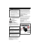
ASSEMBLY Unfold Handlebar WARNING: AVOID INJURY. Read and understand the entire Safety section before proceeding. WARNING: Dropping or tipping over boxed unit could result in personal injury or damage to unit. PACKAGE CONTENTS 3 4 (Figure 4) 1. Remove the lower and loosen the upper hardware on the handlebar assembly. 2. Loosen the hardware on the shift rod. 3. Put the speed selector lever in the sixth forward position. 4. Rotate the handlebars into operating position.
Install Discharge Chute Install Discharge Chute Crank (Figure 5) 1. Remove mounting hardware from the bottom of the chute pedestal. 2. Install discharge chute over opening in the auger housing and secure pedestal to auger housing with hardware removed in step 1. (Figure 6) 1. Slide chute crank through the support bracket. NOTE: Be careful not to damage nylon bushing when attaching crank to the dash. 2. Connect the chute crank to the pinion gear on chute with spring clip pin. 2 3 2 1 1 3 4 3 1 1.
Check Function of Dual Handle Interlock Check Auger Gearcase Oil Without the engine running, press down (engage) both clutch levers. Release attachment clutch lever. Attachment clutch should remain engaged until traction clutch lever is released, then both clutches must disengage. If they do not, contact your dealer for repairs. Check oil level in auger gearcase (see Check Auger Gearcase on page 18). Check Engine Crankcase Oil IMPORTANT: The engine is shipped with 5W-30 oil in crankcase.
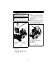
CONTROLS AND FEATURES 3 18 2 1 15 4 19 5 6 17 7 24 9 23 16 14 20 15 10 8 22 11 21 12 25 13 Figure 7 1. Attachment Clutch Lever 2. Speed Selector 3. Traction Drive Clutch Lever 4. Chute Crank 5. Muffler Guard 6. Discharge Chute Deflector 7. Discharge Chute 8. Impeller 9. Auger 10. Scraper Blade 11. Auger Gearcase 12. Clean-out Tool 13. Oil Fill and Dipstick 14. Gas Tank and Cap 15. Recoil Starter Handle 16. Primer Bulb 17. Ignition Switch (Push /Pull) 18. Engine Shutoff Switch 19. Choke 20.
OPERATION Attachment Clutch Right Hand Lever WARNING: AVOID INJURY. Read and understand the entire Safety section before proceeding. 2 WARNING: To avoid injury to hands and feet, always disengage clutches, shut off engine, and wait for all movement to stop before unclogging or working on snow thrower. Keep hands and feet away from auger and impeller. CONTROLS AND FEATURES See Figure 7 for all Controls and Features locations.
Speed Selector Recoil Starter Handle Position the speed selector in the appropriate speed notch to control forward and reverse travel. When pulled, handle will turn engine over. IMPORTANT: DO NOT let handle snap back against starter. See Starting and Shut Off on page 15. Snow Clean-Out Tool (Figure 8) 08000127A 6 1 1 2 OS8225 WARNING: Hand contact with the rotating impeller is the most common cause of injury associated with snow throwers. Never use your hand to clean out the discharge chute.
Discharge Chute Scraper Blade Discharge chute rotates 205°. ALWAYS position discharge chute in safe direction and angle, away from operator and bystanders, before starting engine. The scraper blade allows better contact with the surface being cleared. It also prevents damage to the housing from wear. Discharge Chute Crank IMPORTANT: If chute does not stay in set position, adjust as directed in SERVICE AND ADJUSTMENTS on page 19, or repair before operation.
3. Turn fuel valve on after adding fuel stabilizer. 4. Re-start engine. 5. Run the engine outdoors for 1 minute to be sure that treated gasoline has replaced the untreated gasoline in the carburetor. 6. Slow the engine to an idle speed. 7. Repeat step 1. 5. Check Skid Shoes Check and adjust skid shoes (Skid Shoes on page 19). Allow 1/8 in. (3 mm) between scraper blade and hard, smooth surface(s). Allow 1-1/4 in. (30 mm) between scraper blade and uneven or gravel surfaces. 6.
7. Grasp starter handle and pull rope out slowly until it pulls harder. Let rope rewind slowly. 8. Pull rope with a rapid continuous full arm stroke. Let rope rewind slowly. IMPORTANT: DO NOT let starter handle snap against starter. 9. Repeat steps 7 and 8 until engine starts. (If engine does not start, refer to TROUBLESHOOTING on page 29.) 10. Adjust choke as needed. Electric Start (120V) (920402, 403) 1. Connect extension cord to starter. IMPORTANT: Prevent damage to unit.
MAINTENANCE Ariens dealers will provide any service or adjustments which may be required to keep your unit operating at peak efficiency. Should engine service be required, contact an Ariens dealer or an authorized engine manufacturer's service center. The chart below shows the recommended maintenance schedule that should be performed on a regular basis. More frequent service may be required. MAINTENANCE SCHEDULE WARNING: AVOID INJURY. Read and understand the entire Safety section before proceeding.
CHECK CLUTCH OPERATION CHECK AUGER GEARCASE Auger / impeller must stop within 5 seconds when attachment clutch/impeller brake lever is released. Wheels must stop quickly when traction drive clutch lever is released. If clutches do not engage or disengage properly, adjust or repair before operation (see Attachment Clutch/Brake Adjustment on page 24 and Traction Drive Clutch Adjustment on page 26).
GENERAL LUBRICATION Grease (Figure 12) Oil IMPORTANT: Wipe each fitting clean before and after lubrication. Do not wipe gearcase filler plug; wiping the gearcase filler plug may remove thread sealant and cause leaks. IMPORTANT: DO NOT allow grease or oil to get on friction disc, friction plate or belts. NOTE: Apply Ariens Hi-Temp Grease or equivalent to the lubrication fittings. See SERVICE PARTS on page 28. The unit should be lubricated (Figure 12) at beginning of season or every 25 operating hours.
For Replacement: 1. Align shear bolt holes in auger with shear bolt holes in the shaft. 2. Drive shear bolt through hole (if shear bolt was broken this will drive remaining part from shaft). 3. Secure shear bolt with nut. 1 DISCHARGE CHUTE DEFLECTOR 2 1. Skid Shoe 2. Skid Shoe Hardware OS0482 (Figure 15) Deflector must stay in selected position while throwing snow. To adjust, loosen then retighten the wing knob to desired tension.
DISCHARGE CHUTE (Figure 16) If discharge chute does not stay in position while operating, tighten nut on carriage bolt at pivot point to increase tension on spring. 1 e. Shift speed selector into first reverse speed. f. Engage the traction clutch. Unit should move backward. g. Shut off unit. 7. Adjust pivot pin on the shift rod as necessary so unit travels forward when speed selector is in first forward position and travels backward when speed selector is in first reverse position. 8.
4. Remove spring pin from chute crank and separate. 5. Remove belt finger by removing cap screws mounting belt finger to engine (Figure 19 or 20). 6. Remove attachment drive belt from engine sheave (it may be necessary to turn engine sheave using recoil starter handle). IMPORTANT: With the clutch lever engaged, the belt finger located opposite the belt idler must be less than 1/8 in.
1/8 in. (3.2 mm) (Maximum) 1 1 3 2 2 OS8170 1. Swing Gate Spacer 2. Swing Gate Finger 3. Drive Plate 1. Belt Finger 2. Belt Figure 21 Figure 20 OS8165 TRACTION DRIVE BELT REPLACEMENT (Figures 18, 19, 20, 21 and 22) NOTE: Housing and frame must be tipped apart and attachment drive belt removed from engine sheave in order to change traction drive belt. CAUTION: Always support the frame and blower housing when loosening the cap screws holding them together.
ATTACHMENT CLUTCH/BRAKE ADJUSTMENT WARNING: IMPROPER ADJUSTMENT could result in unexpected movement of auger and impeller causing death or serious injury. AUGER / IMPELLER MUST STOP within 5 seconds when attachment clutch/impeller brake lever is released. 4. With the attachment clutch disengaged, check that the attachment idler arm lightly touches the frame. 5. Tighten jam nut on cable adjustment barrel. With the attachment clutch disengaged, check the attachment idler arm position here.
2. Adjust cable length (Figure 26). a. Loosen jam nut on cable. b. To increase spring extension, adjust barrel down the cable and tighten jam nut. c. To decrease spring extension, adjust barrel up the cable and tighten jam nut. Roller should be 1/2 – 7/8 in. (12.7 – 22.2 mm) from the frame when the attachment clutch is engaged. Check Attachment Brake Figure 25 OS8080 Adjust the Attachment Clutch Cable Spring Extension (Figure 26) 1. Check the attachment clutch cable spring extension.
Check Belt Finger Clearance (Figure 28) 1. With clutch lever engaged, the belt finger located opposite the belt idler must be less than 1/8 in. (3.2 mm) from belt, but not touching the belt. To adjust belt finger, loosen the bolts and move the finger to the proper position. Tighten the bolts and recheck the belt finger clearance. 2. Replace the belt cover and tighten hardware. Check belt finger clearance here. With the attachment clutch engaged, there should be less than 1/8 in. (3.
10. Remove three screws holding friction disc to carrier bearing. 11. Remove old friction disc. Put the new friction disc in place, cup side to carrier bearing. 12. Reinstall three screws into new friction disc and carrier bearing. Torque to 5 – 6 lbf-ft. (6.8 – 8.13 N•m). 1 2 4 3 8 5 7 4 6 3 1. Traction Drive Clutch Cable 2. Adjustment Barrel 3. Jam Nut 4. Adjustment Pivot Pin 5. Speed Selector Arm 6.
SERVICE PARTS STORAGE Order the following parts through your dealer: WARNING: AVOID INJURY. Read and understand the entire Safety section before proceeding. Part No. Description 00036800 Ariens Hi-Temp Grease (3, 3 oz. cartridges) SHORT TERM 21547400 Spark Plug IMPORTANT: NEVER spray unit with high pressure water or store unit outdoors. Run with attachment clutch engaged a few minutes after each use to free unit of any loose or melting snow. Close fuel shut-off valve.
TROUBLESHOOTING PROBLEM Engine will not crank/start. Engine stops. PROBABLE CAUSE CORRECTION 1. Fuel tank is empty. 2. Fuel shut-off valve closed. 3. Build up of dirt and residue around governor/carburetor. 4. Key switch not in run position. 5. Engine start switch turned off. 1. Fill fuel tank. 2. Open fuel shut-off valve. 1. Out of fuel. 2. Fuel shut-off valve closed. 3. Mechanical jam in auger or impeller. 1. Fill fuel tank. 2. Open fuel shut-off valve. 3. Clean area around governor/carburetor. 4.
TROUBLESHOOTING PROBLEM Unit throws snow poorly or does not throw snow. PROBABLE CAUSE 1. Shear bolts broken. 2. Attachment clutch/brake not adjusted properly. 3. Auger is frozen in place. 4. Ice or debris is obstructing auger. 5. Attachment drive belt slipping, worn or damaged. GB - 30 CORRECTION 1. Replace shear bolts (see Shear Bolts on page 20). 2. Adjust attachment clutch/brake (see Attachment Clutch/Brake Adjustment on page 24). 3. Move unit to a warm place to thaw. 4.
SPECIFICATIONS Model Number Description Engine Gross Torque* - ft-lbs (N-m) 920402 920403 Sno-Tek 24 Sno-Tek 28 LCT Storm Force LCT Storm Force 9.5 (12.9) 9.5 (12.9) *Engine output stated in gross torque per SAE J1940 as rated by engine manufacturer. Displacement - in. (cc) 12.7 (208) 12.7 (208) High Idle - RPM (min) 3600 ± 50 3600 ± 50 Start Fuel Tank Capacity - qt (Liters) 120 V 120 V 3.8 (3.6) 3.8 (3.6) Chute Chute Rotation Angle 205° 205° Rotation Control 2.5X Quick Turn 2.
Sno-Tek™ Two-Year Limited Warranty Ariens Company (Ariens) warrants to the original purchaser that Sno-Tek brand products will be free from defects in material and workmanship for a period of two years after the date of purchase. An authorized Ariens dealer will repair any defect in material or workmanship, and repair or replace any defective part, subject to the conditions, limitations and exclusions set forth herein.
Exclusions – Items Not Covered by This Warranty • • • • • • Engines and engine accessories are covered only by the engine manufacturer’s warranty and are not covered by this warranty. Parts that are not genuine Ariens service parts are not covered by this warranty and may void the warranty. Damages resulting from the installation or use of any part, accessory or attachment which is not approved by the Ariens Company for use with product(s) identified herein are not covered by this warranty.
Ariens Company 655 West Ryan Street Brillion, WI 54110-1072 920-756-2141 www.ariens.com Sno-Tek Cover Waterproof, washable and tear-resistant, this cover protects your Sno-Tek when it is not in use. Non-Abrasive Skid Shoes Protect the decorative surfaces around your home. Sno-Tek LCT® Engine Maintenance Kit Includes Ariens 32oz. 5W30 engine oil, Spark Plug, Fuel stabilizer and a spare ignition key. Drift Cutter Extend the bars to cut through drifts and direct snow into the auger.