February 2013
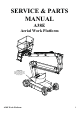
SERVICE & PARTS MANUAL A38E Aerial Work Platform Nameplate The Serial Number of the Work Platform is also stamped on the inside of the Chassis, close to the Steering Cylinder.
NOTES: ii A38E Work Platform
Foreword Introduction HOW TO USE THIS MANUAL This manual is divided into 7 Sections, one of which is in a loose leaf format. The right hand pages of each Section is marked with a black tab that line up with one of the thumb index tabs on the right side of this page. You can quickly find each Section without looking up the Table of Contents which follows this page. The section number printed at the top corner of each page can also be used as a quick guide.
Foreword NOTES: iv A38E Work Platform
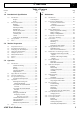
Section Contents i Table of Contents Section No. 1.0 Introduction & Specifications 1.0 1.1 1.2 1.3 2.0 Introduction ........................................................ 1-1 Purpose ..........................................................1-1 Scope ..............................................................1-1 General Information .......................................... 1-1 Platform ..........................................................1-1 Control Box ..................................
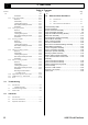
Contents Section i Table of Contents Section No. 4.15 4.16 4.17 4.18 4.19 4.20 4.21 4.22 5.0 5.1 5.2 7.0 Page No. Illustrated Parts Breakdown 7.0 7.1 7.2 Introduction ........................................................ 7-1 Index ..................................................................... 7-1 Illustrated Parts Breakdown .......................... 7-2 Final Assembly A38E ..................................................7-2 Chassis Assembly ....................................
Section Contents i List of Illustrations List of Tables Figure No. Title 1-1 A38E Work Platform ......................................1-1 1-1 A38E Work Platform Specifications ............1-3 2-1 2-2 Forklifting & Lifting The A38E ....................2-1 Manual Brake Release ...................................2-2 3-1 Controls & Indicators ................................... 3-4 3-1 3-2 3-3 3-4 Controls & Indicators ................................... 3-5 Emergency Lowering ..................
Section i Contents NOTES: IV A38E Work Platform
Section Introduction & Specifications 1.0 Introduction PURPOSE The purpose of this Service & Parts Manual is to provide instructions and illustrations for the operation and maintenance of the A38E Work Platform manufactured by Snorkel. (See Figure 1-1). SCOPE The manual includes the procedures and responsibilities which must be strictly adhered to for proper operation, maintenance, adjustment, and repair of this product. The Maintenance Section further covers preventative maintenance and trouble shooting.
Section 1.1 Introduction & Specifications DRIVE & STEER SYSTEMS A38E PURPOSE & LIMITATIONS The A38E Work Platform is restricted to low speed drive when the Platform is raised above the Boom Rest Limit Switch. The Traction controller controls the application of drive from the Joystick by means of two Traction Motors, which are assembled to the drive wheels via a Drive Reduction Gearbox. The purpose of the A38E work platform is to provide a quickly deployable variable height work platform.
Introduction & Specifications 1.2 Specifications ITEM Duty Cycle Platform Size METRIC 45% of 8 hour shift 0.58 m x 1.3 m (inside gaurdrails) IMPERIAL (ANSI) 45% of 8 hour shift 1.77 ft x 4.3 ft (inside gaurdrails) 215 kg Indoors 2 People 2 People Outdoors 1 People 2 People 13.45 m 11.45 m 0.65 m 44.12 ft 37.56 ft 2.13ft 6.10 m 20.00 ft 5.40 m 17.72 ft Stowed Dimensions Length Width Height 4.04 m 1.50 m 2.00 m 13.25 ft 4.92 ft 6.56 ft Ground Clearance 0.12 m 0.
Section 1.
Section Machine Preparation 2.1 Front Lifting / Tie-down Lug 2.1 Preparation for use CAUTION Read, understand and follow all operating instructions before attempting to operate the machine. Lubricate machine per lubrication instructions in Section 4.4, Maintenance. 2. Fully lower the platform and make sure the machine is stowed securely. 3. Check that the hydraulic oil level is adequate and that it is not over filled.
Section 2.6 Machine Preparation When the A38E is on the Truck it should then be made secure. 1. 2. 4. Chock the wheels of the A38E. Secure the work platform to the transport vehicle with chains or straps of adequate load capacity attached to the lifting lugs on the chassis. Secure the top boom at the closest point to the platform to the transport using straps. 3.
Machine Preparation Section 2.
Section 2.
Operation 3.0 Introduction GENERAL FUNCTIONING WARNING To understand the properties of the A38E Work Platform it is recommended that you refer to the Hydraulic and Electrical Schematics in Section 6. All the information within this Service & Parts Manual should be read thoroughly and fully understood. Before beginning to operate the machine it is also a mandatory requirement to read, fully understand and follow the Operators Manual.
Section 3.0 Operation It will be noticed that on the Upper Control Box a set of buttons are used to alternate functions. Each function will have it’s corresponding graphic. This selector switch indicates to the Controller which function is required and by using the Joystick the speed of this selected function can be adjusted.
Operation 3.1 Safety Rules and Precautions WARNING Before using the A38E Work Platform it is imperative to read, understand and follow the following Safety Rules and Precautions. Section 3.1 DO NOT use in winds exceeding 12.5 m/s (28 mph Beaufort Force 6) NEVER change or modify operating or safety systems. INSPECT the machine thoroughly for cracked welds, loose hardware, hydraulic leaks, damaged control cable, loose wire connections and wheel bolts.
Operation Section 3.2 3.2 Controls and Indicators The controls and indicators for operation of the A38E Work Platform are shown in Figures 3-1 & 3-2. The name and function of each control and indicator are listed in Tables 3-1. The index numbers in the figure correspond to the index numbers in the table. The operator should know the location of each control and indicator and have a thorough knowledge of the function and operation of each before attempting to operate the unit.
Operation Section 3.
Operation Section 3.3 3.3 Pre-Operation Inspection WARNING 15. 16. Carefully read, understand and follow all safety rules and operating instructions. Perform the following steps each day before use. DO NOT perform service on Work Platform with the platform elevated unless the elevating assembly is properly supported. 1. 2. 3. 4. 5. 6. 7. 8. Remove module covers and inspect for damage, oil leaks or missing parts.
Operation 3.4 Operation NOTE: Before operating the A38E Work Platform it is imperative that the Pre-Operation Inspection (Section 3.3) has been completed and any deficiencies have been corrected. The operator must also understand the functions of all the controls before operating the machine. ELEVATING & LOWERING THE A38E WORK PLATFORM Before beginning any operation involving the Elevating Assembly the following checks should be carried out.
Section Operation 3.4 5. To “STEER” the A38E activate the Interlock Switch while pushing the Steering Switch LEFT or RIGHT to turn the wheels. Observe the tyres while manoeuvring to ensure proper direction. NOTE: Steering is not self-centring. The wheels must be returned to the straight ahead position by operating the Steering Switch. TRAVEL WITH WORK PLATFORM ELEVATED WARNING Travel with platform elevated ONLY on firm and level surfaces.
Operation ensure a slow controlled rate of descent at all times. Descent can be halted at any time by removing pressure from the red knob. Repeat the operation if necessary for the upper boom when cylinder is in reach of the ground. With both main booms lowered fully it should then be possible to leave the platform safely. 1. 3. Figure 3-2: Emergency Lowering CONTROL FROM GROUND LEVEL 1. 2. Chassis Controls are fitted at the base of the Elevating Assembly.
Section 3.
Operation Section 3.
Section 3.
Maintenance 4.0 Introduction WARNING Be sure to read, understand and follow all information in the Operation Section of this manual before attempting to operate or perform service on any A38E Work Platform. This section contains instructions for the maintenance of the A38E Series Work Platform. Procedures for scheduled maintenance and repair/ removal are included. Referring to Section 3.0 and Section 6.
Maintenance Section 4.1 Preventative Maintenance Table Key Interval Daily = each shift or every day 10h/7d = every 10 hours or 7 days 50h/30d = every 50 hours or 30 days 250h/6m = every 250 hours or 6 months 500h/1y = every 500 hours or 1 year 1000h/2y = every 1000 hours or 2 years Y=Yes/Acceptable N=No/Not Acceptable R=Repaired/Acceptable Preventative Maintenance Report Date : _______________________________ Owner : ______________________________ Model No : ____________________________ V.I.
Maintenance 4.2 Battery Maintenance Electrical energy for the motor is supplied by eight 6 volt batteries wired in series to give a 48 volts DC supply. Each of these batteries consist of three cells which can supply a maximum voltage of 2.1V ea =>6.3V per battery =>50.4V per battery pack. Proper care and maintenance of the batteries and motor will ensure maximum performance from the work platform. WARNING Hazard of explosive gas mixture.
Section 4.3 Maintenance All Snorkel battery operated Work Platforms, including the A38E can operate at ambient temperatures to a value of -20ºC (-4ºF). However for this there are two provisions which must be met. The ISO#46 grade of hydraulic oil normally used in Snorkel Work Platforms must be replaced with a grade suitable for these low temperature conditions.
Maintenance 4.4 Lubrication Section 4.4 PIVOT PINS Refer to Table 4-1 and Figure 4-1 for location and lubrication intervals required for the items that necessitate lubrication service. Refer to the appropriate sections for lubrication information on the Hydraulic Oil Tank and Filter. Apply grease liberally to the Pivot Pin and Pin Lock Plate locations using a brush or cloth. Force as much grease as possible between the Pins & Pin Lock Plates and the Weldments. Wipe away all excess grease.
Section Maintenance 4.5 2. Provide a suitable container to catch the drained oil. Hydraulic tank has a capacity of 25 Litres (6.5 Gallons US). Remove the drain plug on the lower side and allow all oil to drain. Clean the magnetic drain plug and reinstall. Disconnect the return hose and hose fitting from inlet port of the hydraulic return filter. Loosen and remove the filter cover retaining bolts. Remove filter (10 micron) assembly. Replace with a new filter.
Section Maintenance SLEW CROSS-LINE RELIEF VALVES 1. 2. 3. 4. 5. 6. 7. Repeat steps 1-3 as outlined above Loosen Locknuts on both cross-line relief valves and turn adjusting screws anticlockwise two full turns. Operate slew function from lower controls and rotate the Elevating Assembly until the slew stop prevents further rotation. Slowly turn the cross-line relief valve adjusting screw clockwise using a 4 mm Allen key until the pressure gauge reads 50 Bar (725 p.s.i.) pressure.
Maintenance Section 4.7 4.7 Switch Adjustments (Figure 4-7 & 4-8) TILT SENSOR Function: This limit switch is activated when the internal sensor in the ‘Tilt Sensor’ is tilted 3° or more (factory set at this value). When the Tilt Sensor activates the elevating and telescope extend functions will be locked out and an audible warning alarm will sound. It will activate if the Chassis tilts 3° in any direction.
Section Maintenance 4.
Section Maintenance 4.8 4.8 Hydraulic Manifold (Figure 4-9) Though it is not necessary to remove the manifold to perform all maintenance procedures, a determination should be made as to whether or not the manifold should be removed before maintenance procedures begin. REMOVAL 1. 2. 3. Disconnect the Battery Disconnect Plug. Remove the cover from the Chassis body. Tag and disconnect the solenoid valve leads from the solenoids. Tag, disconnect and plug hydraulic hoses.
Section Maintenance 1. 2. 3. 4. 5. 6. 7. 8. 9. 10. 11. 4.
Section Maintenance 4.9 4.9 Hydraulic Pump (Figure 4-10) 4.10 Traction Motor Maintenance (Figure 4-11) CAUTION CAUTION If the hydraulic reservoir has not been drained, suitable means for plugging the hoses should be provided to prevent excessive fluid loss. Before carrying out any maintenance procedures on the Drive Motors ensure that the electric circuit is disconnected i.e. disconnect the batteries and unplug the charger.
Section Maintenance 4.10 Every 1000 working hours, or every two years Every 500 working hours, or annually Brushes - Check the wear, the correct seating, and the regularity of the working surface. Springs - They should not be burned or damaged, and they must apply a constant and equal pressure on the brushes. Bearings- All the bearings are fitted with a double shield and lubricated with high temperature grease. Check for leaks, vibration and noise.
Section Maintenance 4.11 4.11 Electric Motor (Figure 4-13) WARNING Before carrying out any maintenance procedures on the electric motor ensure that the electric circuit is disconnected i.e. disconnect the batteries and unplug the charger. It is also important that when dealing with batteries the proper safety precautions are adhered to. There is always a hazard of sparks or explosive gas. DISASSEMBLY 1. 2. 3. 4.
Section Maintenance 3. 4. 5. 6. 7. 8. 9. Place the bearing spring into the bearing bore. Take a complete armature assembly, including bearings, and insert commutator end bearing into the bearing bore. Note: Do not reuse bearings which have been removed from armature shaft. Keep assembly in a vertical position. Use extreme care not to damage armature with bearing pullers. New bearings should be installed by pressing inner race of bearing onto proper position on armature shaft.
Section Maintenance 4.11 11 6 5 10 7 9 8 3 4 2 1 16 1. 2. 3. 4. 5. 6. 7. 8. Pump Bearing Pulley End Cover Pulley End Bearing Armature Commutator Bearing Stator Housing 9. 10. 11. 12. 13. 14. 15. 16.
Maintenance 4.12 Drive Reduction Gearbox (Figure 4-14) As with most gearboxes oil changes must be carried out at regular intervals. Initially this should be done after the first 50/100 working hours and then subsequently every 500 working hours or at least every 12 months. For this gearbox the minimum recommended viscosity index is 95.
Section Maintenance 4.13 CHANGING THE OIL Unless an oil suction system can be used, it is necessary to remove the gearbox to fully drain the oil. 1. The A38E should be driven for five minutes in order to bring the oil up to working temperature. 2. The Electric Traction Motor must be disconnected from the Gearbox. WARNING Disconnect the batteries when working near the traction motors. 3. 4. 5. 6. 7. 8. 9. 10. 11. 12. 13.
Section Maintenance 4.14 4.14 Lower Lift Cylinder (Figure 4-15) 4 REMOVAL CAUTION 3 2 The Lower Lift Cylinder is heavy, so utilise appropriate lifting equipment to support the unit before removing pins. 1 1. 2. 5 3. 4. 7 5. 6 8 6. Ensure that the A38E is on firm level ground, the Elevating Assembly is completely stowed, the Keyswitch is to the ‘OFF’ position and the Emergency Stop Button is pressed.
Section Maintenance 4.14 with filtered compressed air. Check all threaded parts for stripped or damaged threads. Check the bearing surfaces inside of the headcap, outer edge surface of the piston, inside of the cylinder barrel and the shaft for signs of scoring, pits, excessive wear or polishing. Scratches or pits deep enough to catch a fingernail are unacceptable. Polishing is a sign of uneven loading and if sufficiently polished the affected parts should be replaced.
Section Maintenance 4.15 Upper Lift Cylinder (Figure 4-17) 4.15 2 1 REMOVAL CAUTION 7 The Upper Lift Cylinder is heavy, so utilise appropriate lifting equipment to support the unit before removing pins. 3 5 4 1. 2. 3. 4. 5. 6. Ensure that the A38E is on firm level ground, the Elevating Assembly is completely stowed, the Keyswitch is to the ‘OFF’ position and the Emergency Stop Button is pressed. Provide a suitable container to collect the hydraulic fluid, then disconnect the hydraulic hoses.
Section Maintenance 4.16 5. 6. 7. end of thread and secure with circlip. Lubricate the piston seal and install the piston and rod assembly in the barrel tube. Thread headcap onto barrel tube and hand tighten, then turn 1/4 turn further. Install the upper cylinder Overcentre valve. 4.16 Telescopic Cylinder (Figure 4-18) REMOVAL 1. INSTALLATION NOTE: Before installing Lift Cylinder check cylinder pins and bearings for wear and replace if necessary. 1. Install barrel end bearing (if removed) 2.
Maintenance CLEANING AND INSPECTION 1. 2. 3. 4. Clean all metal parts in solvent and blow dry with filtered compressed air. Check all threaded parts for stripped or damaged threads. Check the bearing surfaces inside of the headcap, outer edge surface of the piston, inside of the cylinder barrel and the shaft for signs of scoring, pits, excessive wear or polishing. Scratches or pits deep enough to catch a fingernail are unacceptable.
Section Maintenance 4.17 CLEANING AND INSPECTION 1. 2. 3. 4. Clean all metal parts in solvent and blow dry with filtered compressed air. Check all threaded parts for stripped or damaged threads. Check the bearing surfaces inside of the headcap, outer edge surface of the rod & piston assembly or inside of the cylinder barrel and the shaft for signs of scoring, pits, excessive wear or polishing. Scratches or pits deep enough to catch a fingernail are unacceptable.
Maintenance 4.18 Master Levelling Cylinder (Figure 4-20) REMOVAL 1. 2. 3. 4. 5. 6. Ensure that the A38E is on firm level ground, the Elevating Assembly is completely stowed, the Keyswitch is to the ‘OFF’ position and the Emergency Stop Button is pressed. Provide a suitable container to collect the hydraulic fluid, then disconnect the hydraulic hoses. Immediately plug hoses to prevent foreign material from entering. Remove securing bolts and pin lock plates from the rod end cylinder pin.
Section Maintenance 4.19 DISASSEMBLY (Refer to Figure 4-16) 4.19 Slave Levelling Cylinder (Figure 4-21) 1. REMOVAL 2. 1. 3. Ensure that the A38E is on firm level ground, the Elevating Assembly is completely stowed, the Keyswitch is to the ‘OFF’ position and the Emergency Stop Button is pressed. Provide a suitable container to collect the hydraulic fluid, then disconnect the hydraulic hoses. Immediately plug hoses to prevent foreign material from entering.
Maintenance INSTALLATION NOTE: Before installing the Slave Cylinder check cylinder pins and bearings for wear and replace if necessary. 1. Install barrel end bearing (if removed) 2. Lift the barrel end of the cylinder into place. NOTE: Take care in aligning the holes so that the barrel end pivot pin can be pushed in by hand. If holes are not properly aligned and the pin is forced in, the bearings will be damaged. 3.
Section Maintenance 4.20 4.20 Adjustment of Overcentre Valves on A38E Lift Cylinders (Figure 4-22) The valve supplier delivers the Overcentre valve preset to specification and SHOULD NOT be adjusted by the user. In the event of the valve having been tampered with the advisable course of action is to fit a replacement cartridge. A short term solution is to temporarily adjust the valve as follows :a) Place the max. SWL (Safe Working Load), evenly distributed, in the cage.
Maintenance Section 4.21 4.21 START UP / CALIBRATION OF THE MOBA OVERLOAD CELL. START UP Storage of the dead load (tare) and the limit value (alarm) 1. MRW LIMIT has been mounted and the control cable is connected. 2. The supply voltage has been applied and the system is switched on. 3. The platform is unloaded and it has been ensured that the platform has no base contact. 4. Remove the program connector’s dust protection cap. 5. Connect the Teach in Handset. 6.
Section 4.
Troubleshooting Section 5.0 5.0 Introduction GENERAL PROCEDURE The following section on troubleshooting provides guidelines on the types of problems users may encounter in the field, helps determine the cause of problems, and suggests proper corrective action. As all problems which require troubleshooting will to some extent be unique, the Service Engineer will need to evaluate the steps to follow for each individual case. Troubleshooting, however, should be carried out in a logical thoughtful manner.
Section Troubleshooting 5.1 PROBLEM PROBABLE CAUSE All functions 1. Blown Electric inoperable. Fuse. Electric 2. Faulty Battery motor does Charger. not start. 3. Faulty Battery or Batteries. REMEDY Check fuses, Replace if blown. Check the voltage output of battery charger. If less than 24 VDC, repair or replace. After completely charging batteries test each battery. Replace as required. 4. Loose or broken Check continuity of all Battery Lead. battery and motor leads. Replace if necessary. 5.
Section Troubleshooting PROBLEM PROBABLE CAUSE prime the brake lines. 5. Drive Reduction Gearbox has seized due to lack of oil. 6. Brake Valves out of adjustment. 7. Joystick damaged or faulty. Cage 1. Air in cage levelling is levelling closed erratic or circuit. irregular 2. Cage damaged, throughout hole centres are the lift cycle. out of position. 3. Damaged Overcentre valves on master /slave cylinders. Machine 1. Faulty Steering will not Switch on steer. Joystick. 2.
Section 5.2 Troubleshooting 5.2 Fault Codes. The A38E is equipped with a fault detection system, if you have a faulty component, bad electrical connection or start up error a fault code will be displayed on the read out located on the upper control box. For fault codes 01 - 39 the following procedure should be followed. Ensure that no selector buttons are depressed. Ensure that the deadman switch on the joystick is not held. Ensure that the joystick is in neutral.
Troubleshooting 02 22 23 24 25 26 27 28 29 31 32 34 36 37 38 39 51 52 53 54 55 56 57 58 59 61 62 63 64 65 66 67 68 69 5.
Section 5.
Schematics Section 6.0 6.0 Introduction This section contains electrical and hydraulic power schematics and associated information for maintenance purposes. INDEX Electrical Assy, J1 Harness Electrical Assy, J2 Harness Electrical Assy, J1 Harness & Connections Hydraulic Legend Hydraulic Schematic A38E Work Platform Page 6.3 6.4 6.5 6.9 6.
Section 6.
A38E Work Platform A5 A6 A7 A8 A9 A10 A11 A12 5 6 7 8 9 10 11 12 FROM C4 WHITE/BLACK 20 40b A A FROM C4 WHITE/BLACK 20 40a 20 FROM A12 37 NOT USED ORANGE GREY NOT USED BROWN BLACK GREEN A1 B 1 C1 127 (5.0") 203 (8.0") 546 (21.5") ORANGE/VIOLET RED/WHITE A4 4 RED/WHITE BLACK/ORANGE A3 3 NOT USED A2 2 RED A1 COLOR 1 ITEM NO.
A1 F 12 12 12 4 3 27 15 35 23 24 34 11 13 14 7 30 J K 21 L 26 T U M 25 18 G S V N 2 A 16 F R P E 6 B 24 D C 6.1. Electrical Schematics 33 19 31 J2 Harness 8 9 28 17 32 6.
Re f A B C D E F G N am e I n s u l at e d S p a d e B lu e I n s u l at e d S p a d e R e d M 5 R in g B lu e M 8 R in g B lu e 8 O h m R e si st o r R e d S p ad e M ale 24V R e lay A38E Work Platform P art N u m b e r 501140- 000 510130- 000 513113- 000 510170- 000 513346- 000 510142- 000 510086- 000 TOP VIEW C ab l e C o l o ur/W i re Le n gth 1 R e d / 200m m 2 R e d / 925m m 3 B l ack / 1040m m Si ze 3.5m m 3.5m m 3.
Section 6.
A38E Work Platform Snorkel MOBA OVERLOAD CELL Electrical Schematic Schematics 6-7 Section 6.
6-8 TOP VIEW Electrical Schematic Schematics A38E Work Platform Section 6.
Section Schematics 6.2 6.2. Hydraulic Schematics Table 6-2: Hydraulic Schematic Legend REFERENCE NAME BRK Brake. CLRV CV CYL1 CYL2 CYL3 CYL4 CYL5 CYL6 FL1 HP MMB MOT1 MP V1 V2 V3 V4 V5 V6 V7 V8 V9 FUNCTION Spring applied - hydraulically released brakes to stop rotation of drive wheels. (Set at 100 Bar). Cross-line To limit the max. operating relief valve. pressure of the slew motor. (Set at 50 Bar). Check Valve.
Section 6.
FL1 TELE V6 STEER V5 SLEW V4 V2 V1 BRAKE T1 Figure 6-3, 4 : Hydraulic Schematic V3 CV CLRV CLRV B1 BRK BRK CLRV MMB - B5 V4 B6 V8 V7 Main Manifold Block B2 A38E Work Platform BOOM2 V7 A1 V2 BOOM1 V8 B5 B3 RESEVOIR / HYDRAULIC TANK V9 A5 V1 (RV) B4 V9 V5 V6 HP A4 HP M B3 B4 MP B2 A3 A3 V10 A2 A4 P B6 B A TP A1 MMB A6 MOT1 CYL3- TELE A2 TP V13 CYL2- BOOM2 V3 C B A V11 V12 A6 F B B V11 B A BRAKE A E C E CYL1- BOOM1 A5 V14 F
6-12 NOTES: 6.
Illustrated Parts Breakdown 7.0 Introduction 7.1 Index This section lists and illustrates the replaceable assemblies and parts of the A38E Work Platform as manufactured by Snorkel UK. Assembly Each parts list contains the component parts for that assembly indented to show relationship where applicable. Section 7.2 7.1 Page Final Assembly A38E .................................................. 7-2 Chassis Assembly ...................................................... 7-4 Booms and Posts Assembly ...
Section Illustrated Parts Breakdown 7.2 FINAL ASSEMBLY A38E 500200-001 (ANSI Version) 500200-000 (CE Version) ITEM PART NO.
Illustrated Parts Breakdown A38E Work Platform Section 7.
Section Illustrated Parts Breakdown 7.2 CHASSIS ASSEMBLY A38E 500202-000 ITEM PART NO.
Illustrated Parts Breakdown A38E Work Platform Section 7.
Section Illustrated Parts Breakdown 7.2 BOOMS & POSTS ASSEMBLY 500201-000 ITEM PART NO.
Illustrated Parts Breakdown A38E Work Platform Section 7.
Section Illustrated Parts Breakdown 7.2 CAGE & CRADLE ASSEMBLY(STANDARD) 057603-000 (501864-000 is not included as part of this assembly) (ANSI is Without Overload) ITEM PART NO. 1 2 3 4 5 6 7 8 9 10 11 12 13 14 15 057521-003 508931-000 057523-000 501864-000 010076-000 501970-000 058251-000 057347-001 501886-000 056066-012 056069-016 503101-045 056069-012 058494-040 501971-000 DESCRIPTION CAGE RAIL ASSY. DROP BAR ASSY.
Section Illustrated Parts Breakdown 7.
Section Illustrated Parts Breakdown 7.2 CAGE ROTATOR ASSEMBLY(OPTION) 500905-000 (501864-000 is not included as part of this assembly) (ANSI is Without Overload) ITEM PART NO.
Illustrated Parts Breakdown Section 7.
Section Illustrated Parts Breakdown 7.2 WHEEL HUB ASSEMBLY 057669-000 ITEM PART NO. 1 2 3 4 5 6 7 8 9 057665-000 057664-000 057662-000 057663-000 057585-000 057584-000 057583-000 057582-000 057669-002 7-12 DESCRIPTION WHEEL HUB HINGE THRUST BEARING PIVOT BOSS PIVOT PIN COVER PLATE OUTER HUB BEARING INNER HUB BEARING STUD PLASTIC BUSHING QTY.
Illustrated Parts Breakdown A38E Work Platform Section 7.
Section Illustrated Parts Breakdown 7.2 DRIVE REDUCTION GEARBOX ASSEMBLY 057580-000 ITEM PART NO. 1 2 3 4 5 6 7 8 9 10 11 12 13 14 15 16 17 18 19 20 21 22 23 24 25 26 27 28 29 30 31 32 - NOTE: 7-14 DESCRIPTION COUPLING EXPANSION PLUG STEEL DISC BRONZE DISC O-RING SPACER O-RING ANTI-EXTRUS. RING PISTON SPRING O-RING ANTI-EXTRUS.
Illustrated Parts Breakdown A38E Work Platform Section 7.
Section Illustrated Parts Breakdown 7.2 TRACTION MOTOR ASSEMBLY 057568-000 : RIGHT HAND MOTOR 058834-000 : LEFT HAND MOTOR ITEM PART NO. 1 2 3 4 5 6 7 8 9 10 11 12 13 14 15 16 057698-000 057699-000 057569-001 057569-000 7-16 DESCRIPTION MOTOR MOUNTING FACE SEAL CIRCLIP BEARING COOLING FAN COMMUTATOR BEARING FIELD WINDINGS COMMUTATOR COVER BRUSH BOXES SUPPORT END FACE VENT / INSPECTION CAP BRUSH BRUSH SPRINGS TACHO ADAPTOR KIT TACHO QTY.
Illustrated Parts Breakdown A38E Work Platform Section 7.
Section Illustrated Parts Breakdown 7.2 MOTOR/PUMP ASSEMBLY 057530-000 ITEM PART NO. 1 * 2 3 4 5 6 7 8 9 10 11 12 13 14 15 16 17 058862-000 058862-001 058847-000 058863-000 - NOTE: 7-18 DESCRIPTION HYDRAULIC PUMP SEAL KIT COUPLING OIL SEAL PUMP MOUNTING FACE CIRCLIP BEARING CIRCLIP CIRCLIP COOLING FAN COMMUTATOR BEARING COMMUTATOR COVER BRUSH HOUSING SUPPORT BRUSH END HOUSING TERMINAL BLOCK VENT / INSPECTION CAP QTY.
Illustrated Parts Breakdown A38E Work Platform Section 7.
Section Illustrated Parts Breakdown 7.2 REAR & FRONT WHEEL KIT (WHITE - NON MARKING) SERIAL 1297 TO CURRENT 500494-000 ITEM PART NO. 1 2 3 4 057578-000 057668-001 057666-000 057667-003 DESCRIPTION WHEEL NUT - M14 REAR WHEEL TYRE & RIM ASSY. WHEEL NUT - M16 FRONT WHEEL TYRE & RIM ASSY. QTY. 10 2 10 2 REAR & FRONT WHEEL KIT (NON MARKING) ITEM PART NO. 1 2 3 4 057578-000 058971-000 057666-000 058970-000 DESCRIPTION WHEEL NUT - M14 REAR WHEEL TYRE & RIM ASSY.
Illustrated Parts Breakdown A38E Work Platform Section 7.
Section Illustrated Parts Breakdown 7.2 SLEW MOTOR, WORM DRIVE UNIT & SLEW BEARING ASSEMBLY 500284-001 ITEM PART NO. 1 500284-000 * * 2 * * * 500280-000 500281-000 500285-000 500285-001 500282-000 056021-012 7-22 DESCRIPTION A38E WORM DRIVE UNIT & SLEW BEARING ASSEMBLY BOLT 5/8” -11 UNC x 3 1/2” WASHER M16 HARDENED A38E SLEW MOTOR SEAL KIT BOLT 1/2” -13 UNC x 1” WASHER M12 SPRING QTY.
Illustrated Parts Breakdown A38E Work Platform Section 7.
Section Illustrated Parts Breakdown 7.2 MANIFOLD BLOCK ASSEMBLY 500261-000 ITEM PART NO.
Illustrated Parts Breakdown A38E Work Platform Section 7.
Section Illustrated Parts Breakdown 7.2 LOWER LIFT CYLINDER ASSEMBLY 504504-000 ITEM PART NO. 1 2 500397-000 DESCRIPTION CYLINDER BODY EMERGENCY LOWERING VALVE QTY.
Illustrated Parts Breakdown A38E Work Platform Section 7.
Section Illustrated Parts Breakdown 7.2 UPPER LIFT CYLINDER ASSEMBLY 504505-000 ITEM PART NO. 1 2 3 4 5 6 7 8 9 10 11 12 13 14 15 16 17 500397-000 CYLINDER BODY EMERGENCY LOWERING VALVE 058728-000 SEE NOTE SEE NOTE SEE NOTE SEE NOTE SEE NOTE SEE NOTE SEE NOTE 057048-000 SINGLE OVERCENTRE VALVE END CAP ROD AND END PIVOT U-RING ROD SEAL ROD SEAL WIPER BACK UP 0-RING O-RING SPACER PISTON O-RING PISTON HEAD PISTON SEAL PISTON LOCKNUT WASHER GREASE NIPPLE NOTE: 7-28 DESCRIPTION QTY.
Illustrated Parts Breakdown A38E Work Platform Section 7.
Section Illustrated Parts Breakdown 7.2 TELESCOPIC CYLINDER ASSEMBLY 058461-000 ITEM PART NO. 1 2 3 4 5 6 7 8 9 10 11 12 13 14 15 16 058728-000 058714-000 SEE NOTE SEE NOTE SEE NOTE SEE NOTE 057048-000 SEE NOTE SEE NOTE - NOTE: 7-30 DESCRIPTION QTY. CYLINDER BODY SINGLE OVERCENTRE VALVE SINGLE P.O.
Illustrated Parts Breakdown A38E Work Platform Section 7.
Section Illustrated Parts Breakdown 7.2 STEERING CYLINDER ASSEMBLY 058463-000 ITEM PART NO. 1 2 3 4 5 6 7 8 SEE NOTE SEE NOTE SEE NOTE SEE NOTE 057048-000 DESCRIPTION CYLINDER BODY CYLINDER ROD PISTON SEAL END CAP WIPER ROD SEAL O-RING GREASE NIPPLE QTY. 1 1 1 1 1 1 1 2 NOTE:ITEMS 3, 5, 6 & 7 FORM THE SEAL KIT FOR THE A38E STEERING CYLINDER.
Illustrated Parts Breakdown A38E Work Platform Section 7.
Section Illustrated Parts Breakdown 7.2 MASTER/SLAVE CYLINDER ASSEMBLY MASTER CYLINDER 058734-000 SLAVE CYLINDER 058735-000 ITEM PART NO.
Illustrated Parts Breakdown A38E Work Platform Section 7.
Section Illustrated Parts Breakdown 7.2 PUMP & TRACTION MOTOR CONTROL UNIT ASSEMBLY 501862-000 ITEM PART NO. 1 2 3 4 5 6 7 501863-001 501873-000 501874-000 501875-000 501876-000 501877-000 501878-000 DESCRIPTION ECU BOX WITH PC BOARD LINE CONTACTOR PUMP CONTACTOR MOTOR CONTACTOR FWD & REV MOTOR CONTROLLER FUSE BLOCK FUSE QTY. 1 1 1 1 1 1 1 HARNESSES ITEM PART NO.
Illustrated Parts Breakdown A38E Work Platform Section 7.
Illustrated Parts Breakdown Section 7.2 A38E LOWER CONTROL BOX ASSEMBLY 500490-000 (Harnesses are not part of this assembly) ITEM 1 2 3 4 5 6 7 8 9 10 11 12 13 14 15 16 17 PART NO. DESCRIPTION QTY 501871-000 501867-000 508033-000 SEE NOTE SEE NOTE 501872-000 SEE NOTE 501867-000 PCB ASSY, GROUND CONTROL E-STOP SWITCH C/W CONTACT BLOCK CONTACT BLOCK N.C.
Illustrated Parts Breakdown Section 7.
Illustrated Parts Breakdown Section 7.2 UPPER CONTROL BOX ASSEMBLY 501864-000 ITEM PART NO.
Illustrated Parts Breakdown Section 7.
Section Illustrated Parts Breakdown 7.2 CABLES & ELECTRICAL COMPONENT LEGEND ITEM PART NO. DESCRIPTION 1 058834-000 DRIVE MOTOR, LH 2 057568-000 DRIVE MOTOR, RH 3 501864-000 UPPER CONTROL BOX ASSY.
Illustrated Parts Breakdown A38E Work Platform Section 7.
Section Illustrated Parts Breakdown 7.2 HOSE ASSEMBLY 500360-000 ITEM PART NO.
Illustrated Parts Breakdown A38E Work Platform Section 7.
Illustrated Parts Breakdown Section 7.2 DECAL KIT American English (ANSI) 500206-001 ITEM PART NO.
Illustrated Parts Breakdown Section A38E Work Platform 6 34 17 13 4 29 12 35 21 36 10 37 8 7 7 8 INSIDE 31 9 36 37 26 7.
7-48 511069-000 501870-000 512224-000 511067-000 510280-000 511099-000 510215-000 057430-002 510220-001 511027-000 510218-000 058881-001 510216-000 058186-000 510982-000 511114-000-NL 501869-000 510221-000 504199-005 058860-000 510217-000 511115-200 058531-200 058531-200 010076-901 060197-001 0070540 513792-000 DUTCH CE 510207-000 511069-000 501870-000 512224-000 511067-000 510280-000 511099-000 510848-000 057430-002 512236-000 511027-000 512234-000 058881-001 512232-000 058186-000 510982-000 511114-000-
Illustrated Parts Breakdown Section 27 22 4 A38E Work Platform 6 15 21 9 11 13 14 19 12 23 18 24 17 10 27 26 22 10 8 20 7 7 8 25 26 22 7.
Illustrated Parts Breakdown Section 7.2 OPTION LIST ITEM PART NO. 1 2 3 4 058191-000 058191-001 058275-000 058284-000 DESCRIPTION A38E OPTION, POWER TO PLATFORM 110V A38E OPTION, POWER TO PLATFORM 220V A38E OPTION, FLASHING BEACON A38E OPTION, SPOTLIGHT IN PLATFORM The options outlined opposite are available from Snorkel when ordering a new machine or as a spare part to be retrofitted to an existing machine.
Illustrated Parts Breakdown Section 7.
Local Distributor / Lokaler Vertiebshändler / Distributeur local El Distribuidor local / ll Distributore locale EUROPE, MIDDLE EAST AFRICA & ASIA PHONE: +44 (0) 845 1550 058 FAX: +44 (0) 845 1557 756 NORTH & SOUTH AMERICA PHONE: +1 785 989 3000 TOLL FREE: +1 800 225 0317 FAX: +1 785 989 3070 AUSTRALIA PHONE: +611300 700 450 FAX: +61 2 9609 3057 NEW ZEALAND PHONE: +64 6 3689 168 FAX: +64 6 3689 164