This Manual Must Be Read Before Operating The Equipment Owner / Operator’s Manual Spreaders for Snow & Ice Control FOR MODELS SR-110 Wireless Accurate Flow SR-210 Wireless Multi-Purpose New Plug & Perform Technology Easy As 1-2-3 Installation State of The Art Wireless Control Simple Push Button Operation CUSTOMER COPY Protected by the following patents, #6,089,478, #6,088,865, #Des.425,915 and other pending U.S. and foreign patent applications.
This Page Intentionally Left Blank 1—2 © Trynex International 2009 L1600
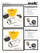
Box Inventory Model # SR-110 / SR-210 SR-110 Box Contents B ITEM DESCRIPTION A) B) C) Spinner Drive Assembly Hopper Gate Deck/Hopper Support Hardware Pack Receiver Mount Hopper Support Tube D) E) A C F) G) Key Fob Transmitter QTY 1 1 1 1 1 1 1 D E F G SEE KEY FOB ILLUSTRATION TO THE RIGHT SR-210 Box Contents ITEM DESCRIPTION A) Spinner Drive Assembly Hopper B) Lower Hopper Support C) B A D) E) F) Hardware Pack Receiver Mount G) Key Fob Transmitter Hopper Support Tube QTY 1 1 1 1 1 1 1
Vehicle Trailer Plug Activation Information Model # SR-110 / SR-210 STOP 1. Verify that your vehicle has a 7-way RV style trailer plug on vehicle. 2. If your vehicle is equipped with the proper plug continue to pages 5 and 6 3. you can continue with the installation. 4. If you do not have power, consult your vehicle owner’s manual trailering section for more information. If this does not resolve your problem, contact your nearest auto/truck dealer or trailer hitch installation center. 5.
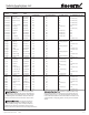
Vehicle Application List Model # SR-110 / SR-210 MAKE MODEL YEAR FACTORY PLUG AVAILABLE? AFTERMARKET PLUG REQUIRED FACTORY PLUG AFTERMARKET PLUG Chevrolet Colorado 04 & Newer Yes NA See Note *(1) NA Chevrolet Blazer S-Series 05 & Prior NA Yes NA See Note **(2) Chevrolet Blazer K-Series 94 & Prior NA Yes NA See Note **(2) Chevrolet S-10 04 & Prior NA Yes NA See Note **(2) Chevrolet K-1500 - K-3500 99 & Prior NA Yes NA See Note **(2) Chevrolet Silverado 99 & Prior
Vehicle Application List Continued Model # SR-110 / SR-210 MAKE MODEL YEAR FACTORY PLUG AVAILABLE? AFTERMARKET PLUG REQUIRED FACTORY PLUG AFTERMARKET PLUG GMC Yukon 02 & Current Yes NA See Note *(1) Pg 19 NA GMC Savana 02 & Current Yes NA See Note *(1) Pg 19 NA GMC G-Series Van 02 & Current NA Yes NA See Note **(2) Pg 19 Hummer H2 03 & Current Yes NA NA See Note ****(4) Hummer H2 Sut 06 - Current Yes NA NA See Note ****(4) Hummer H3 06 - Current Yes NA Nothing
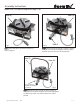
Assembly Instructions Model # SR-110 (refer to diagram on page 1-10) Item (A) Item (A) Fig 1. Fig 2. Step 1: Place item (A) on level working surface as shown in figure 1. Item (F) Hitch pin with clip supplied with hardware bag item (D) Item E Step 2: Mount item (E) to item (A) as shown in figure 2. Using (4) 1/2” lock nuts and tighten securely in place with 3/4” socket or wrench to 75 Foot pounds. Item (A) Fig 3. Step 3: Mount item (F) to item (A) as shown in figure 3.
Assembly Instructions Model # SR-110 (refer to diagram on page 1-10) Fig 1. Gate deck/hopper support item (C) Fig 2. Hopper item (B) Item (F) Step 4: Install item (C) to item (F) as shown in figure 1. Using (2) 5/16” hex bolts and (2) 5/16”lock nuts supplied in hardware bag item (D). Tighten securely in place with 1/2” socket or wrench to 18 foot pounds. Step 5: Mount item (B) to item (F) as shown in figure 2.
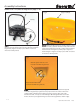
Assembly Instructions Model # SR-110 (refer to diagram on page 1-10) Fig 1. Cable mounting bracket located in item (D) hardware bag Gate Adjustment Knob See Drawing Below Support item (F) Step 7: Mount control bracket to item (F) using existing hopper mounting hardware as shown in figure 1. Cable should be looped as shown in figure 1 if mounted to this way. When mounting in a remote location, be sure to leave a large radius in cable so it will not bind or kink.
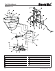
Parts Breakdown Model #SR-110 Key 1 — 10 Par t No. Des c r iption D 6081 5/16" Fender Washer D 6133 5/16" - 18 x 1/2" Hex Bolt D 6138 5/16" Locknut D 6166 5/16" - 18 x 1" Hex Bolt D 6302 Gate Knob D 6072 T-Handle Cable - 5' D 6305 Bulkhead Cable Fitting Assembly D 6308 5/16" - 16 x 3/4" Bolt Assy. w/Hole D 6462 5/16" - 18 x 1-3/4" HHCS D 6703 Gate Indicator / Stop Qty. 4 2 14 3 1 1 1 1 12 1 Key Par t No.
Complete Drive Assembly Parts Breakdown Model # SR-110 Key A 4005 Complete Drive Assembly Part No. D 6084 D 6079 D 5535 D 4135 D 6062 T 15043 D 6067 D 6122 D 6467 D 6064 D 6078 D 6232 D 6715 D 6071 D 6063 D 6750 D 6110 D 6463 D 6398 D 6405 D 6131 D 6061 © Trynex International 2009 L1600 Description Antenna #10-32 x 1/2” HHMS W/Washer 1/2-13 Serrated Flange Nut Hair Pin Clip 2 Inch Mounting Tube Weldment Hitch Pin 7-Way Spreader Harness #10-32 x 5/8” Serr. Flng.
Assembly Instructions Model # SR-210 (refer to diagram on page 1-15) Item (A) Item (A) Fig 1. Fig 2. Step 1: Place item (A) on level working surface as shown in figure 1. Item (F) Hitch pin with clip supplied with hardware bag item (D) Item E Step 2: Mount item (E) to item (A) as shown in figure 2. Using (4) 1/2” lock nuts and tighten securely in place with 3/4” socket or wrench to 75 foot pounds. Item (A) Fig 3. Step 3: Mount item (F) to item (A) as shown in figure 3.
Assembly Instructions Model # SR-210 (refer to diagram on page 1-15) Fig 2. Fig 1. Auger with set screw in hardware bag item (D) Lower hopper support item (C) Item (F) Step 4: Place auger on transmission shaft so that the set screw hole lines up with the upper flat on shaft as shown in figure 1. Thread set screw into hole until it makes contact with the flat on the transmission shaft. Make sure the set screw is set to the upper part of the flat.
Assembly Instructions Model # SR-210 (refer to diagram on page 1-15) 1 — 14 © Trynex International 2009 L1600
Parts Breakdown Model # SR-210 Key © Trynex International 2009 L1600 Par t No. Des c r iption D 6081 3/8" Fender Washer D 6138 5/16" Locknut D 6462 5/16" - 18 x 1-3/4" HHCS D 6754 2.7 cu/ft Salter Hopper Yellow D 6066 Hopper Throat Support D 6065 Main Tube Support Qty.
Complete Drive Assembly Parts Breakdown Model # SR-210 Key A 4005 Complete Drive Assembly 1 — 16 Part No. D 6084 D 6079 D 5535 D 4135 D 6062 T 15043 D 6067 D 6122 D 6467 D 6064 D 6078 D 6232 D 6715 D 6071 D 6063 D 6750 D 6110 D 6463 D 6398 D 6075 D 6131 D 6061 Description Antenna #10-32 x 1/2” HHMS W/Washer 1/2-13 Serrated Flange Nut Hair Pin Clip 2 Inch Mounting Tube Weldment Hitch Pin 7-Way Spreader Harness #10-32 x 5/8” Serr. Flng.
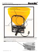
Electrical System Model # SR-110 / SR-210 BATTERY NEG (-) ANTENNA BYPASS BATTERY POS (+) MOTOR POS (+) MOTOR NEG (-) LEARN LED COMMON Wireless Receiver Connections Battery Power Positive (+) Terminal #4 Black Wire Spreader Power Plug End View Battery Ground Negative (-) Terminal #1 White Wire © Trynex International 2009 L1600 1 — 17
Key Fob Programming / Bypass Function Model # SR-110 / SR-210 Programming a New Key Fob Transmitter Apply power to the spreader unit (Spreader plugged into the 7 -way connector and typically vehicle running.) Press the Learn / Bypass switch to the Learn position for 2 seconds and release. Move clear of the spreader and keep hands and feet away from the spreader. Press and hold the 50% button on the key fob transmitter to be learned until the spreader starts.
General Information Model # SR-110 / SR-210 CONGRATULATIONS! The spreader you have purchased is an example of snow and ice control technology at its finest! Your spreader’s self-contained design is a trademark of all Snowex products. Here’s why... SIMPLICITY: Fewer moving parts manufactured of higher quality means minimal maintenance for your SnowEx spreader.
Safety Introduction Model # SR-110 / SR-210 This manual has been designed for your help. It will assist you and instruct you on the proper set-up, installation and use of this spreader. Refer to the table of contents for an outline of this manual. We require that you read and understand the contents of this manual completely (especially all safety information) before attempting any procedure contained herein. Extra copies of Owner/Operator Manuals can be purchased at your Snowex Dealer.
Safety Model # SR-110 / SR-210 Before attempting any procedure in this book, these safety instructions must be read and understood by all workers who have any part in the preparation or use of this equipment. For your safety ,warning and information decals have been placed on this product to remind the operator of safety precautions. If anything happens to mark or destroy the decals, please request new ones from Snowex. Remember, most accidents are preventable and caused by human error.
Safety Model # SR-110 / SR-210 Never exceed 45 m.p.h. when loaded spreader is attached to vehicle. Braking distances may be increased and handling characteristics may be impaired at speeds above 45 m.p.h. Never use wet materials, or materials with foreign debris with any of these spreaders. These units are designed to handle dry, clean, free-flowing material. Note: Can not spread water softener salt. Never leave material in hopper for long periods of time.
Wireless General Information Model # SR-110 / SR-210 This device complies with Part 15 of the FCC rules. Operation of this device is subject to the following two conditions. (1) This device may not cause harmful interference, and (2) This device must accept any interference received, including interference that may cause undesired operation. This equipment has been tested and found to comply with the limits for a Class B digital device, pursuant to Part 15 of the FCC Rules.
Spreader Maintenance and Operation Model # SR-110 / SR-210 t WARNING – When servicing is necessary, perform it in a protected area. Do not use power tools in rain or snow because of danger of electrical shock or injury. Keep area well lit. Use proper tools. Keep the area of service clean to help avoid accidents. t WARNING – Disconnect electricity to spreader before servicing. t CAUTION – There are no serviceable parts in the motor/transmission assembly. Any attempt to service will void warranty.
Troubleshooting Model # SR-110 / SR-210 SPREADER DOESN'T RUN FUSE BLOWN JAMMED AGITATOR AGITATOR INTERFERENCE FIX OR REPLACE MATERIAL ISSUE TOO MUCH AMP DRAWN BAD MOTOR/TRANS ASSEMBLY BAD MOTOR CHECK WITH TEST KIT TEST GOOD NO LOAD 4-20 AMPS TEST BAD 20+ AMPS BAD TRANSMISSION CHECK WITH TEST KIT BAD ELECTRICAL CONNECTION CORROSION AT CONNECTION LOOSE CONNECTION DEAD SHORT IN WIRING ELECTRICAL CONNECTION TEST DIRECT POWER (12 VOLTS) TO MOTOR TEST TURN SHAFT BY HAND SHOULD TURN FREELY CLEAN
Available Optional Accessories Model # SR-110 / SR-210 UTM-175 TRL-175 UTILITY MOUNT TRAILER MOUNT TPM-175 THREE POINT MOUNT DRM-175 DROP UTILITY MOUNT 1 — 26 D - 6306 20’ CABLE EXTENSION EXC-020 HOPPER COVER © Trynex International 2009 L1600
Warranty Limited Warranty Snowex products are warranted for a period of two years from the date of purchase against defects in material or workmanship under normal use and service, subject to limitations detailed below. Warranty period of two years begins on the date of purchase by the original retail user. The WARRANTY REGISTRATION CARD must be returned to the manufacturer for this warranty to become effective. This warranty applies to the original retail purchaser only.
800-837-0159 Don’t Forget To Visit Our Website !! www.snowexproducts.com to register your product and receive a FREE “How To” spreading guide.