
User guide

© Trynex International 2009 L1600
1 — 13
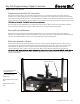
Assembly Instructions
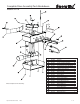
Model # SR-210 (refer to diagram on page 1-15)
Fig 1.
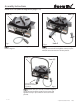
Fig 2.
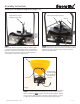
Fig 3.
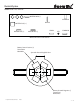
Auger with set screw in
hardware bag item (D)
Lower hopper support item (C)
Mounting bolt,
washer and lock
nut. Located in
hardware bag
Item (D)
Step 4:
Place auger on transmission shaft so that the set screw
hole lines up with the upper at on shaft as shown in gure
1. Thread set screw into hole until it makes contact with the
at on the transmission shaft. Make sure the set screw is set
to the upper part of the at. Complete tightening the set
screw into place with a 5/32” allen wrench.
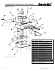
Step 5:
Mount item (C) to item (F) as shown in gure 2. Using
(2) 5/16” hex bolts and (2) 5/16” lock nuts supplied in hardware
bagitem (D). Tighten securely in place with 1/2” socket or
wrench to 18 foot pounds.
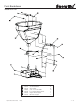
Step 6:
Mount item (B) to item (F) using (4) 5/16” hex bolts, fender washers
and 5/16” lock nuts supplied in hardware bag item (D). Fender washers
must be installed on inside
of hopper to provide proper support. Tighten
securely in place with 1/2” socket or wrench to 18 foot pounds. See page
1-7 gure 2 for more information on how to properly install hopper.
Item (F)
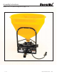
Hopper item (B)
Item (F)