
User guide


© Trynex International 2009 L1600
1 — 8
Assembly Instructions
Model # SR-110 (refer to diagram on page 1-10)
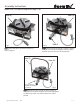
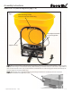
Fig 1.
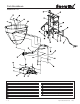
Fig 2.
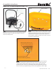
Fig 3.
Gate deck/hopper support item (C)
Material agitator with set screw
Located in hardware bag Item (D)
Step 4:
Install item (C) to item (F) as shown in gure 1. Using
(2) 5/16” hex bolts and (2) 5/16”lock nuts supplied in hardware
bag item (D). Tighten securely in place with 1/2” socket or
wrench to 18 foot pounds.
Step 5:
Mount item (B) to item (F) as shown in gure 2. Using
(4) 5/16” hex bolts, (4) fender washers and (4) 5/16” lock nuts
supplied in hardware bag item (D). Fender washers must be
installed inside the hopper to provide proper support as
shown in gure 2. Tighten securely in place with 1/2” socket
or wrench to 18 foot pounds.
Step 6:
Mount item (B) to item (C) using (2) 5/6” hex bolts and (2) washers supplied
in hardware bag item (D). Tighten securely in place with 1/2” socket or wrench to
18 foot pounds. Mount material agitator by placing it on the upper part of the
transmission shaft. Line up set screw with upper at and tighten with a 5/32” allen
wrench. Be sure to put agitiation nger so that it is facing upward as shown in g 3.
Item (F)
Hopper item (B)
Hopper bolts with washers
Located in hardware bag Item (D)