
User guide


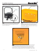

© Trynex International 2009 L1600 1 — 9
Assembly Instructions
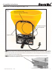
Model # SR-110 (refer to diagram on page 1-10)
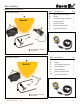
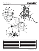
Fig 1.
Support item (F)
Cable mounting bracket
located in item (D) hardware bag
Step 7: Mount control bracket to item (F) using existing hopper mounting hardware as shown in gure 1. Cable should be
looped as shown in gure 1 if mounted to this way. When mounting in a remote location, be sure to leave a large radius in
cable so it will not bind or kink. You can also mount the control bracket on a vehicle using (2) 5/16” hex bolts and (2) 5/16”
lock nuts supplied in item (D) hardware bag.
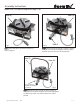
Gate Adjustment Knob
See Drawing Below
Step 8: Material ow can be adjusted with moving the locking knob forward or backward to increase or decrease
the amount of material to be applied to an area.