Î GE Fanuc Automation Programmable Control Products t Genius Hand-held Monitor User’s Guide GFK-0121E June 1994
GFL–002 Warnings, Cautions, and Notes as Used in this Publication Warning Warning notices are used in this publication to emphasize that hazardous voltages, currents, temperatures, or other conditions that could cause personal injury exist in this equipment or may be associated with its use. In situations where inattention could cause either personal injury or damage to equipment, a Warning notice is used. Caution Caution notices are used where equipment might be damaged if care is not taken.
Preface Related Publications Content of this Manual Chapter 1. Introduction: Chapter 1 describes the Hand-held Monitor. This chapter lists catalog numbers and specifications. It also explains compatibility between different versions of the Hand-held Monitor and various other products. Chapter 2. Hardware Setup: Chapter 2 gives instructions for powering the HHM, changing its EPROM, and changing its battery pack.
Preface designers, operators, maintenance personnel, and others using Field Control I/O modules. This book contains a detailed description, specifications, and installation instructions for all currently–available I/O modules. Genius I/O PCIM User’s Manual (GFK-0074). Reference manual for the PCIM, which interfaces a Genius bus to a suitable host computer. This book describes the installation and operation of the PCIM.
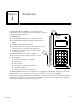
Contents Chapter 1 Introduction . . . . . . . . . . . . . . . . . . . . . . . . . . . . . . . . . . . . . . . . . . . . . . . 1-1 Hand-held Monitor Description . . . . . . . . . . . . . . . . . . . . . . . . . . . . . . . . . . . . 1-2 HHM Compatibility . . . . . . . . . . . . . . . . . . . . . . . . . . . . . . . . . . . . . . . . . . . . . . . 1-4 HHM Specifications ......................................... 1-5 Ordering Information . . . . . . . . . . . . . . . . . . . . . . . . . . . . . . . .
Restarts for autonumbers that do not restart in each chapter. figure bi level 1, reset table_big level 1, reset chap_big level 1, reset1 app_big level 1, resetA figure_ap level 1, reset table_ap level 1, reset figure level 1, reset table level 1, reset Chapter these restarts must be in the header frame of chapter 1.
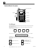
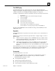
1 Hand-held Monitor Description Mode Select Keyswitch GENIUS mon Hand Held Monitor cfg GE Fanuc LCD Display HHM Cable F1 F2 F3 F4 7 8 9 Home 4 5 6 Y Menu 1 2 3 Clear + – 0 D On Off Function Keys Decimal Keys Operation Keys Connection for Charger/Adapter The HHM Keypad The Hand-held Monitor keypad has three types of keys: function keys (F1 - F4), decimal keys, and operation keys.
1 The HHM Display The Hand-held Monitor has a 4-line LCD screen. On a new Hand-held Monitor, displays are in English. The display language can easily be changed to French, German, or Italian. (Instructions for changing the display language are on page 3-5). In addition to alphanumeric characters, the display uses the following special characters: IT OT 4 1 O C BS ? * tri-state input. Output with Feedback, or block with both inputs and outputs. circuit is forced OFF. circuit is forced ON.
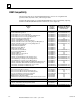
1 HHM Compatibility The following table shows which Hand-held Monitor versions are compatible with specific Genius I/O, Field Control, and related products. Note that the functionality of an older Hand-held Monitor can be upgraded by replacing its firmware PROM. (PROM installation instructions are in chapter 2).
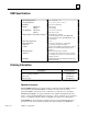
1 HHM Specifications Operatingtemperature Storagetemperature Humidity Weight: without case with case Size (HxWxD): without case with case Required AC power (for battery charger) Fully chargedoperation Displaycharacters Keyboard Features Displaylanguage Drop Test Data Rates 0–60 C(32–140 F) –40 to +70 C(–40 to 158 F) 5-95% (non-condensing) 1.3 lbs (0.6 Kg) 1.8 lbs (0.8 Kg) 8.00” x” 3.75 x” 1.25 (cmx) 10.85” x 4.30” x 2.25” 115/230V AC 15%, 47-63 Hz (16-hour charging period for IC660BPM500B.
Chapter 2 Hardware Setup 2 Power for the Hand-held Monitor The Hand-held Monitor can be operated using its built-in battery, or connected to either 115 volt or 230 volt AC power. A battery pack must always be installed to operate the HHM, even when using AC power. An optional 230VAC Power Adapter can be used to connect the Hand-held Monitor Charger to variety of 230 VAC power outlets. See page 2-2 for more information.
2 Using the 230VAC Power Adapter The optional 230VAC Power Adapter (IC660MCA512) can be used to connect the Handheld Monitor Charger to variety of 230 VAC power outlets by means of a standard computer cable (not supplied). The Adapter has a receptacle on the top for the Hand-held Monitor Charger and an IEC 320 receptacle on the side for the computer cable. HHM Charger receptacle in top of Adapter IEC 320 receptacle in side of Adapter Instructions 1.
2 Battery Operation The HHM’s battery pack provides up to 6 hours of operation. To maximize battery life, allow the battery to discharge fully between charges. The battery should be allowed to fully discharge once a month. Low Battery Power Low battery power may cause this message: * * L O W B A T T E R Y * * * * H H M H A L T E D * * P l e a s e R e c h a r g e Or the display may blank, or two black lines may appear briefly. Low battery power suspends the current operation.
2 Changing the PROM New features can be added to upgrade a Hand-held Monitor by replacing its PROM as described below. Caution To prevent possible damage to the Hand-held Monitor, this operation should be performed in an area equipped with suitable electrostatic discharge protection. 1. If the HHM is connected to AC power, disconnect it. 2. Remove the HHM battery pack as described on the previous page. 3.
2 7. If necessary, bend the pins on the PROM so they line up properly with the holes in the socket. Bend the pins by pressing each side against a clean desk or table top as shown below. If possible, a conductive mat should be used. 46024 Conductive mat 8. Insert the EPROM or Battery-Backed RAM into the socket. IMPORTANT: Inserting the PROM backward can damage the Micro PLC and destroy the PROM.
2 Permanent Installation If the Hand-held Monitor is to be installed using the metal bracket provided, follow the instructions below. Do not install the HHM yet if it will be used to configure I/O blocks. The mounting bracket provided can be used to install the Hand-held Monitor behind a panel. You will need to make a cutout in the panel for the HHM (see next page). You will also need to install a connector for the Hand-held Monitor within reach of the HHM’s cable.
2 HHM Installation Instructions 1. Select a suitable location for the HHM. Environmental specifications are listed on page 1-5. The location must have 115 VAC or 230 VAC power. 2. Cut an opening 3.75I (9.53cm) wide x 8I (20.32cm) high in the panel. Drill four mounting holes as shown below. 4.38in (11.13cm) 3.75in (9.53cm) 1.00in (2.54cm) Cutout 6.00in (15.24cm) 1.00in (2.54cm) 3. Attach the bracket to the HHM with the screws, washers, and lockwashers provided.
2 Installing the D-Shell HHM Connector Follow the instructions below if you are installing the supplied D-shell connector on the bus. 1. Using the mounting plate as a template, cut an opening in the panel for the mating connector. Also drill two holes for the mounting hardware. 2. Attach the mounting plate and mating connector to the panel using the mounting hardware supplied. 3. Secure the two ends* of the serial bus cable to the back of the panel using strain relief brackets. 4.
2 Installing a Separate Hand-held Monitor Connector You can add a connector to the bus for a permanently-mounted Hand-held Monitor, or to provide an additional attachment point for a portable HHM. The unit shown below (catalog number 44A736310-001-R001) provides a Hand-held Monitor connector and serial bus terminals. .5 in 1.27 cm 1.673 in 4.249cm 46357 Hand-held Monitor Connector Panel Mounting Ear 2.834 in 7.
2 Making the Bus Connections The HHM connector has two sets of terminals; one for incoming cable and the other for outgoing cable. Connect the Serial 1, Serial 2, and Shield In terminal of either connector to the previous device. Connect the Serial 1, Serial 2, and Shield Out terminal of the other connector to the next device. When making bus connections, the maximum exposed length of bare wires should be two inches.
Chapter 3 Getting Started 3 This chapter explains how to: H H Turn on the Hand-Held Monitor h h GFK-0121E the HHM Device Number the HHM Display Language the Host CPU automatic shutoff ability to Change Block ID Parameters ability to Change the Baud Rate of Devices on the Bus ability to Configure Devices on the Bus ability to Force I/O Circuits ability to Clear Faults Test the operation of the Hand-held Monitor.
3 Turning on the Hand-Held Monitor With the battery pack charged, or with the HHM connected to a suitable AC power source, press the ON/Off key to turn the Hand-held Monitor on. Caution 1. If the baud rates match, press F4 (Ok). If the baud rates do not match, press F2 (Change) instead. The HHM screen changes to allow you to select a different baud rate: Do not connect or disconnect the HHM to/from another device or connector while it is ON.
3 Displaying the Home Menu This is the Hand-held Monitor’s Home menu: F 1 : H H M B. Pressing the Home key or DMenu key from a lower-level screen. U T I L I T I E S Use the Home menu to get to any other HHM function, as shown below. F 2 : A N A L Y Z E F 3 : C O N F I G U R A T I O N F 4 : D E V I C E Notice that different screens appear, depending on the type of device that is currently communicating with the HHM. M E M O R Y Display the Home menu by either: A.
3 Configuring the Hand-held Monitor You can change the following operating characteristics of the Hand-held Monitor: H H H H H H H H PLC reference format. 153.6 Kbaud “standard” baud rate. Changing the HHM Device Number The Device Number (serial bus address) assigned to the Hand-held Monitor appears on line 2 of the first HHM configuration screen. Device Number set to 0. English language displays. H H M C O N F I G B L O C K N O . O Shutdown after 10 minutes of inactivity.
3 Changing the HHM Display Language Enabling/Disabling Automatic Shutoff The next display shows the current language selection. The next screen shows whether automatic shutoff is selected. H H M C O N F I G L A N G U A G E E N G L I S H t g l e n t r n x t Press F2 (TGL) to change the display language (French, German, Italian, English). Press F3 (Enter) to save the change.
3 Enabling/Disabling the Ability to Change the Baud Rate of Devices on the Bus Enabling/Disabling the Ability to Force I/O Circuits The next configuration screen shows whether the HHM is able to change the baud rate of bus devices. The next display shows whether the HHM can be used to force I/O circuits. C H N G B L K E N A B L E D C I R C U I T E N A B L E D B A U D To change the current selection, press F2 (Toggle), then press F3 (Enter).
3 Testing Operation of the Hand-held Monitor If you want to test the Hand-held Monitor display, keypad, or internal electronics, select F2 (HHM SELF-TEST) from the HHM Utilities menu. This menu of tests appears: F F F F 1 2 3 4 Testing the Internal Electronics Press F3 (TEST INTRNALS) from the Self-Test menu.
Chapter 4 Device Configuration Overview 4 The Hand-held Monitor can be used to configure (establish the operating characteristics for) a wide variety of other devices. Some configurable devices are: H H H Genius I/O Blocks, High-speed Counter Blocks, and PowerTRAC Blocks the Series 90-70 Remote I/O Scanner and its remote drop Field Control stations. The Hand-held Monitor displays a unique set of configuration screens for each type of configurable device.
4 Online or Offline Configuration Devices can be configured before or after installation on a properly-terminated serial bus. If a new device is to be added to an existing bus running at a baud rate other than 153.6 Kbaud standard, the device must first be configured offline. Be careful adding new devices to existing systems. Be sure the baud rate configured for the new device matches that of the system - never mix baud rates on a bus.
4 Displaying the Configuration Menus The illustration below shows how to reach the HHM’s device configuration menus from the Main Menu. H the Configure Block screens to configure redundancy and Configuration Protection. H For all devices, you will need to select F3 (Configuration) then F1 (Program Block ID) to configure a block’s required features. h h h h Device Number (serial bus address). I/O type for input/output blocks. CPU references.
4 Completing the Program Block ID Screens Select F1 (Program Block ID) from the Configuration menu to complete the mandatory part of a device’s configuration. (The HHM’s CHNG BLK ID capability must be enabled). When the HHM is set up for a PLC host, the Program Block ID screen looks like this: P I B r R / L e O G B L O C K I D O (device references) O C K N O .
4 Configuring a Remote I/O Scanner After selecting the baud rate, the next Program Block ID screen is used to assign data types and lengths for a Series 90-70 Remote I/O Scanner. P % L t R O G R E M O T E M A P I E N G T H ( P T S ) g l r e f s e n d n x t Configuration Notes The Remote I/O Scanner User’s Manual explains remote drop configuration in detail. You should use it as a reference during remote drop configuration. Configuring the Remote Drop To configure the remote drop with the HHM: 1.
4 Configuring Genius Blocks To configure individual features of a Genius block, the block must be the “active” device. Selecting the Active Device them all here. You should refer to the User’s Manual for the device you are configuring for descriptions of its configuration screens and detailed instructions for completing them. 1. From the Analyze menu, select F3 (Block/Bus Status). Configuration Instructions 2. Press F1 (Next) or F2 (Previous), to reach the device’s description screen. 1.
4 Configuring Field Control Station 1. From the HHM Main Menu, display the special set of menus for Field Control. 1. If you want to change the address, enter the new address using the keypad. A. If the Bus Interface Unit or Field Processor is the current-selected device, press F2 (analyze) twice or F3 then F2. 2. Press F4 (entr). An error message appears if the number has been used for another device. B.
4 Configuring Individual Field Control Modules Go to the Field Control configuration menu: F 1 : G E N I U S F 2 : M o d u l e C O N F I G C o n f i g F 2 : P r e v i o u s M e n u Disable the I/O Scan While you configure the modules in the station, you may want to disable I/O scanning. (The Bus Interface Unit or Field Processor begins scanning I/O as soon as it is powered up). P r v > t g l The next screens are used to assign the starting addresses and lengths for I, then Q, then AI, then AQ data.
4 Add Modules and Assign References Assign I/O References for the Module The first module configuration screen looks like this: After you “accept” a module into the slot, a screen like this appears: Slot number Rack number R O: S 1 R O: S 1 I_ E M P T Y I 1 6 e n t r < > t g l r e a d Specify the I/O references to be used by the module. For most applications, you can simply have the BIU/Field Processor assign the next available references in that memory type.
Chapter 5 Monitoring the Bus and its Devices 5 This chapter explains how to perform monitoring and control operations with the Hand-held Monitor. Displaying Information About Bus Devices (page 5-2). h Selecting the Active Device (page 5-2). h Clearing Faults (page 5-3). Monitoring and Controlling Individual Circuits on a GeniusBlock (page 5-8). h Discrete, Relay, High-speed Counter Block (p. 5-9). – Forcing an Input or Output (page 5-9). – Clearing Circuit Faults (page 5-9).
5 Displaying Information About Bus Devices Select F3 (Block/Bus Status) from the Analyze menu to: H H H Line 1 also provides information about the device currently being displayed: Display the references assigned to any device. Display the revision level of any device. Display the description and Global Data address of a bus controller. H Display the fault status of a Genius block or Remote I/O Scanner (remote drop). H H H Select the active device. Clear all faults on the active device.
5 Clearing Faults from the Block/Bus Status Screen Monitoring the Bus Status Pressing the CLEAR key from this screen clears all faults on the active device. For Genius blocks, if you want to clear a specific circuit fault, select F2 (Monitor/Control Reference) from the Analyze menu instead. To display the number of devices currently operating on the bus, and the current bus scan time, select F4 (Bus) from the Block/Bus Status display.
5 Monitoring a Genius Block Select F2 (Monitor Block) from the Analyze menu to: H Display the I/O type of all circuits on the active block. H H Display (not change) forces on the active block. Display the bus presently selected by the BSM Controller. Monitor Block Display for Discrete I/O and Input Blocks For a discrete block, the Monitor Block display shows the I/O type and current state of each circuit.
5 Monitor Block Display for Discrete Relay Output Blocks Monitor Block Display for RTD or Thermocouple Blocks For a Relay block, the Monitor Block screen shows the current open (O) or closed (C) states of all relay outputs: For an RTD or Thermocouple Input block, the Monitor Block screen shows the current values of two inputs at a time. Values reported by the block may be tenths of degrees (Celsius or Fahrenheit), tenths of ohms, or unconverted counts.
5 Monitor Block Display for a High-speed Counter Block For a High-speed Counter block, the Monitor Block function displays a sequence of screens with the following information: Control Inputs Press F1 ( > ) to display the block’s Control Inputs: 1. The states of the block’s four Preset Outputs. C O N T R O L 1 1 1 2 D H P P 1 1 1 1 2. The states of the block’s Control Inputs. 3. The current values of the block’s internal data storage registers: Accumulator, Counts per Timebase, and Strobe.
5 Monitor Block Display for a PowerTRAC Block If the active device is a PowerTRAC block, the HHM’s Monitor Block function displays the following screens: Bit 15 = 1 means the overcurrent event indicated by bit 4 occurred on the auxiliary current line. H One screen showing the states of all of the block’s Status Inputs. H Individual screens showing the block’s current calculated data values. In the Monitor Block function, these values are NOT labelled.
5 Monitoring and Controlling Individual Circuits on a Genius Block Select F3 (Monitor/Control Reference) from the Analyze menu to: H Display the present state or value of any circuit on the active block. H H H H Display the diagnostics status of any circuit. Force and unforce individual circuits. Force a bus switch on a dual bus. Clear individual circuit faults. Basic Monitor/Control Display Format Each Monitor/Control Reference screen provides information about one circuit, channel, or data value.
5 Monitor/Control Reference Display for a Discrete, Relay, or High-speed Counter Block For a discrete, Relay, or High-speed Counter block, the Monitor/Control Reference screen looks like this: M N T R / C N T L (reference) I S T A T E : O N O F A U L T S > o n o f f r e l e s Line 1 identifies the circuit currently being monitored. Pressing F1 ( > ) displays other circuits. Diagnostics Line 3 of the Monitor/Control Reference screen shows whether the circuit has any faults.
5 Monitor/Control Reference Display for an Analog, RTD, or Thermocouple Block For an analog, RTD, or Thermocouple block, the Monitor/Control Reference screen shows the current value for each circuit. For example: M N T R (ckt. reference) I 2 : – 1 9 3 7O N O F A U L T S > f o r c e r e l e s A Diagnostics Line 3 shows whether the circuit has any faults. If it does, one of these messages appears on line 3: Feedback error: There is a wiring error or other hardware fault on a Current-source Analog block.
5 Monitor/Control Reference Displays for a PowerTRAC Block For a PowerTRAC block, the Monitor/Control Reference function displays: H H H 16 screens, each showing the state of one Status Input. This information is more easily displayed with the Monitor Block function,which shows all 16 Status Inputs on one screen. See page 5-7. Individual labelled displays of the block’s current calculated data values. For PowerTRAC block version 2.
5 PowerTRAC Status Inputs Screens PowerTRAC Control Outputs Screens First, the Hand-held Monitor displays 16 screens showing the states of Status Inputs: Finally, the HHM displays 16 screens showing the states of individual Control Outputs (datagram handshaking bits). If you use the F1 ( > ) key to reach the Control Outputs, notice that there are several unused references following the Extra Calculated Data data. You can use F2 (ref) to go directly to output 1.
5 Monitoring/Controlling Remote Drop Data The HHM can display diagnostics and currentI/O states, and force and unforce individual I/O points on I/O modules in a remote drop. When the active device is a Remote I/O Scanner, the HHM’s Monitor Block and Monitor/Control Reference functions display the same set of screens. This is unlike HHM operation for Genius blocks, where the screens for Monitor Block and Monitor/Control Reference are different.
5 Forcing a Circuit Displaying and Clearing Remote Drop Faults (The HHM’s circuit forcing capability must be enabled to perform this function). Display the circuit you want to force. Press F3 (force). To display diagnostics for a circuit, press F4 (diag) from the Monitor screen. If there is a fault, it appears on line 3. For example: For a discrete circuit, the HHM displays: mo n o n o f f D 1 O m r e l e s Press F2 (on) or F3 (off) to force the circuit. The forced state appears on line 3.
5 Monitoring/Controlling Field Control Data The HHM can display diagnostics and currentI/O states, and force and unforce individual I/O points on Field Control modules. 1. From the HHM Main Menu, display the Field Control main menu. F1:Monitor F 2 : C o n f i g u r a t i o n A. If the BIU or Field Processor is the active device, press either F3 (Configuration) or F2 (analyze) twice. B. If it is NOT the active device select F2 (analyze) then F3 (Block/Bus Status).
5 Displaying Field Control Faults A Hand-held Monitor can display faults from a Bus Interface Unit or Field Processor while attached anywhere on the Genius bus. 4. Press F1 to display the first set of 16 faults (one fault at a time). For example: S l o t # 1 F a u l t # 1 E X T R A I / O M O D U L E 1. From the HHM Main Menu, display the Field Control main menu (instructions are on the previous page). F1:Monitor F 2 : C o n f i g u r a t i o n < > e x i t A. Use F1 and F2 to display another fault B.
5 Pulse Testing Outputs on Discrete Genius Blocks Pulse Testing verifies the ability of outputs on a discrete block to change state. Pulse Testing also indicates whether output circuits (wires, power sources, loads) will start or stop current flow. Pulse testing is recommended for blocks controlling outputs that seldom change state. It provides assurance that when needed, an output will operate correctly. Blocks that control outputs which frequently change state do not need to use the Pulse Test feature.
Chapter 6 Reading CPU Memory 6 This chapter explains how to use a Hand-held Monitor to read data in a specified memory location in a Series 90–70, Series Six, or Series Five PLC. New data from the specified memory location is displayed every three seconds. General Instructions _________________________________________ 1. Be sure the Hand-held Monitor is set up for the type of PLC host you want to read data from. (See page 3-5 for instructions). 2.
6 Series 90 PLC For a Series 90-70 PLC, the Hand-held Monitor can read data from %R, %AI, %AQ,%I, %Q, %T, %M, %S, %SA, %SB, %SC, and %G memory. For a Series 90-70 PLC, the memory location/content screen looks like this example: D E V I C E % R t g l M E M O R Y 1 c h n g e n t r When F3 (entr) is pressed, the HHM displays the content in either bit or word format, as appropriate for the selected memory type.
6 Series Six PLC For a Series Six PLC, the Hand-held Monitor can read data from register memory. That includes I/O data mapped into register memory, (it is easier to display I/O data with the HHM’s Monitor Block or Monitor Control Reference function). For a Series Six PLC, the Device Memory screen looks like this example: Enter or Change the PLC Type To enter or change the PLC type: 1. Press F3 (chng). A cursor appears at the left of the colon. For a Series Six PLC, enter the number 32768. 2.
6 Series Five PLC For a Series Five PLC, the Hand-held Monitor can read data from register memory. That includes I/O data mapped into register memory, (it is easier to display I/O data with the HHM’s Monitor Block or Monitor Control Reference function). For a Series Five PLC, the Device Memory screen looks like this example: Enter or Change the PLC Type To enter or change the PLC type: 1. Press F3 (chng). A cursor appears at the left of the colon. For a Series Six PLC, enter the number 32768. 2.
6 Changing the Data Format When the memory display first appears, it looks like this example: D E V I C E M E M O R Y 7 M E M : 1 : 6 5 5 2 4 W O R D 1 2 3 4 5 v a l a d d r You can display either one byte or one word of data. You can also select either decimal display: WO R D 1 2 3 4 5 B Y T E 3 or binary display: 4 4 1 4 4 11 1 4 4 4 4 4 4 11 4 4 4 4 4 4 11 To change the data format: Changing the Selected Address To change the address being monitored, press F3 (ADDR).
Chapter 7 Error Messages 7 This chapter explains error messages that may be displayed on the Hand-held Monitor. Powerup Error Messages #2 The HHM has a faulty EPROM. Obtain a replacement or an HHM upgrade kit. If an error occurs during the Hand-held Monitor’s self-test, this multi-language error display may appear: #4 The HHM may have been assigned a Device Number already used on the bus. Press the ON/OFF key, then disconnect the HHM from the device it is attached to. Press the ON/OFFkey again.
7 Operating Error Messages Configuration Error Messages The HHM may display one of the messages shown below when the ON/OFF key is pressed or during operation. If a message appears, press the Clear key, then follow any action suggested. The following messages may appear while configuring a bus device. They usually indicate an incorrect selection. E: N O A C T I V E A D D R No active device has been selected, so many functions do not operate. See page 5-2 to select an active device.
Index A C AC operation, 2-1 Case, 1-3 AC power required, 1-5 , 2-1 Catalog numbers Genius blocks and HHM versions, 1-4 HHM, options, accessories, 1-5 Accessories, 1-3 Active device, selecting on HHM, 4-6 , 5-2 , 5-4 , 5-8 Adapter 230VAC connector, 2-2 AC power, 2-1 Alarm diagnostic, 5-10 Analog blocks Monitor block screen, 5-5 Monitor/Control Reference screens, 5-10 B Battery pack, 1-3 charging, 2-1 , 2-3 operation, 2-3 replacing, 2-3 Baud rate, 1-5 configuring for bus devices, 4-4 configuring HHM to
Index for analog, RTD, or Thermocouple block, 5-10 Different Baud error, 7-2 viewing present status of circuit on RTD or Thermocouple block, 5-5 Function Disabled error, 7-2 Different Block Types error, 7-2 Dimensions, 1-5 Display, 1-5 special characters, 1-3 testing, 3-7 Duplicate Block Number error, 7-2 Duplicate I/O References error, 7-2 E EEPROM failure, 3-7 EEPROM Failure error, 7-2 Error messages, during HHM test, 3-7 G Genius blocks compatibility with HHM versions, 1-4 I/O type, 5-4 monitoring wi
Index LCD display, 1-1 Loss of I/O Power diagnostic, 5-9 Low power, 2-3 M PowerTRAC block data sequence, 5-11 display data, 5-7 Monitor/Control Reference screens, 5-11 Powerup, 3-2 Powerup Error messages, 7-1 Memory, reading, 6-1 Program Block ID screens, 4-4 Menus, main, 3-3 PROM, changing, 2-4 Monitor Block screens, 5-4 Pulse Testing outputs, 5-17 Monitor Only error, 7-2 Monitor/Control Reference screens for Field Processor, 5-15 for Genius blocks, 5-8 for Remote I/O Scanner, 5-13 Monitoring, men
Index Short Circuit diagnostic, 5-9 Shutoff automatic, 2-3 configuring for HHM, 3-5 U Underrange diagnostic, 5-10 Upgrading the HHM, 2-4 Specifications, 1-5 V T VARs, display for PowerTRAC block, 5-11 Voltage, display for PowerTRAC block, 5-11 Temperature specifications, 1-5 Testing, 3-7 Thermocouple blocks Monitor block screen, 5-5 Monitor/Control Reference screens, 5-10 W Watt-hours, display for PowerTRAC block, 5-11 Wiring Error diagnostic, 5-10 Index-4 GFK-0121E