
Owner's manual


38
H3 using this equation: H3=y/x=(H1+H2)/2
Where x is the reference channel and y the second channel. In theory, all Hx must give the same
result. However, when the FRF contains resonance and/or anti-resonance, the result can vary from
one equation to another. In effect, noise on the X or Y channel on the anti-resonance or resonance
can distort the results. The H1 equation is better when the noise is on the Y channel while the H2
equation gives better results when the noise is on the X channel.
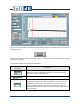
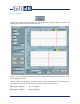
The coherence graph allows determining if the signal measured on both channels is linked. The
equation used for the coherence is:
Coherence=H1/H2=Sxy
2
/(Sxx*Syy)
The Do Graph Autoscale button allows adjusting the Y and X scales of both the FRF and coherence
graphs.
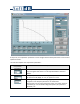
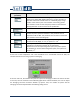
The next table explains the computation parameters:
Computation
parameters
Description
This is the number of lines of the average FRF. Possible selections are
1024, 2048, 4096 or 8192 lines. The FRF calculation is done with a block
size of 2*Nbr Lines.
This is the time window used for the Sxx, Syy and Sxy computation.
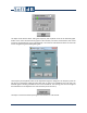
This parameter allows adjusting the overlap between the time blocks
used for the FRF calculation. This parameter can be adjusted from 0% to
90%. This parameter is used to increase the number of block used for the
average calculation and to compensate for the loss of data that causes
the time window. The classic set-up is an overlap of 66% and the Hanning
window.
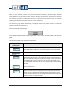
The dB/Lin. parameter allows choosing the amplitude scale format. The
choices are dB or Lin.
This parameter allows selecting the Hx (H1, H2 or H3). Refer to the
beginning of this section for computation technique detail. H1 must be
used if noise is on the second channel while H2 must be used if noise is
on the reference channel. H3 is an average of both H1 and H2 and can be
used if the noise is on both channels.