SOHO RAID SR2000 User’s Manual P/N: P99649 Version: 2.
Chapter 1 Introduction........................................................... 2 1-1 Functions and Features ............................................... 2 1-2 Product Specifications ................................................ 3 1-3 System Requirements and support.............................. 3 1-4 Note (Read carefully before using SR2000)............... 4 Chapter 2 Installation ............................................................. 6 2-1 Package Contents...................................
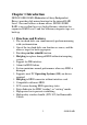
Chapter 1 Introduction SR2000 SOHO RAID (Redundant of Array Independent Drives) provides disk mirror function for the internal RAID Level 1 for small offices or home offices. SR2000 SOHO RAID is an excellent low-cost, high-efficiency substitute for expensive RAID Level 5 and low-efficiency magnetic tape as a back up. 1-1 Functions and Features The two hard disks can simultaneously perform mirroring with synchronization.
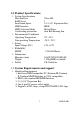
1-2 Product Specifications System Specifications Host Interface RAID level Installation Space HDD Interface HDD Selection Mode Overheating prevention Environmental Conditions Operating Temperature Non operating Temperature Power Input Voltage (DC) Ultra ATA 1 2 x 5-1/4” Expansion Bay EIDE Master/Slave 6cm Ball Bearing Fan 0℃~55℃ -20℃~70℃ +5V, +12V Reliability >250,000 Hours MTBF Dimensions Measures (mm) Weight 146(W)X238(D)X85(H) 1.
Supports the Following OS (no drivers required) DOS, Windows NT Server, Workstation, Windows 98/95/3.1x, NetWare**3.12/4.1x/5.x, SCO UNIX, LINUX (RedHat Slackware, Debian, S.U.S.E., OPENLinux, TURBOLinux), Free BSD, IBM OS/2, Solaris 2.x. 1-4 Note (Read carefully before using SR2000) 1. Use two identical hard disks (same brand name and model) for optimum performance and greatest convenience. 2.
8. Normal HDD mode for SR2000 is Ultra DMA. In the event of failure to work with EIDE connector, HDD will automatically configure itself in PIO mode 4 or with lower speed. 9. There is a 6mm Ball Bearing Fan integrated in the SR2000 to prevent overheating for 7200 rpm HDD. When two 7200rpm Hard Disks are installed in a very busy server, we suggest adopting a PC case with optimal design for overheating prevention in order to avoid PC or RAID crashes. 10.
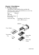
Chapter 2 Installation 2-1 Package Contents Your SR2000 SOHO RAID package includes the following: please contact our distributors in case of any missing or damaged items.
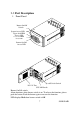
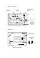
2-2 Part Description Front Panel Buzzer On/Off Switch System Access LED Upper deck HDD Access LED Lower deck HDD Access LED Buzzer On/Off Access LED Lock/Unlock Switch DC 12V Fan SUS 302 Handle Buzzer On/Off switch: Alarm functions when buzzer switch is on. To release the function, please push the button. Push the button again to recover the function. LED displays Red when buzzer switch is Off.
Inside the SR2000 LCD Panel Operation mode switch Controller Select button Upper Deck Removable Carrier Lower Deck Removable Carrier Back Panel EIDE Controller Master/Slave Jumper DC Power Socket Outlet 8 SOHO RAID
2-3 How to open/close the front panel Opening the front panel 1. Touch the right side center of the front panel with your finger as indicated by the arrow. There is a trigger to open the panel. Press Closing the front panel 1. Turn the panel in the direction indicated by the arrow to connect it with the trigger until it clicks inside, which means the front panel is closed.
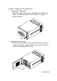
2-4 How to remove/insert the Removable Carrier Removing the Removable Carrier 1. Following the indicated direction, press down and hold the Removable Carrier Handle to unlock the spring from its button. 2. Turn the Removable Carrier Handle in the direction indicated by the arrow to remove the Removable Carrier. 3. Pull out the Removable Carrier along the direction shown in the figure. 1 1. Push in 2. Turn 3.
To insert the Removable Carrier 1. Following the direction indicated by the arrow, slide the Removable Carrier along the rail into the slot end of the upper or lower deck. 2. Following the direction indicated by the arrow, turn the Removable Carrier Handle to the end in order to fix it with the spring. 1. Push in 2. Turn to the end 2. 1.
2-5 Installing HDD in the Removable Carrier Set Master/Slave jumpers to MASTER (factory default). Connect the power cord and the Removable Carrier’s EIDE/IDE interface cable to the HDD. Inset the HDD into the Removable Carrier. Fasten the HDD with the attached 6#-32 screws in their four locations. Place the power cord and the EIDE/IDE interface cable lower than the surface of the HDD in order to avoid any hindrance when taking out the HDD. Please refer to the following illustration.
2-6 Installing the SR2000 in your Computer Turn the power off. Make sure there are two 5-1/4" Expansion bays available for the SR2000. Set up MASTER or SLAVE positions of SR2000 according to your needs. (Factory default: Master). If you need to set it to SLAVE, please modify the jumpers on the back panel of the SR2000. Remove computer case and insert the SR2000 into the Expansion bay. Connect power cord and EIDE/IDE interface cable to the right connector.
Chapter 3 RAID Use After proper installation, the SR2000 can be considered as one HDD. Both FDISK and FORMAT commands have the same function on the two Hard Disks inside the SR2000. Some OS can perform self partitioning and formatting without going through the above mentioned process. After turning PC power on, SR2000’s two hard disks maintain synchronized operation unless one of them stops working.
automatically format HDD synchronously. In addition, it will install the OS and other required software. (Refer to OS Installation Guide) 6. When the two installed hard disks have different capacities, SR2000 will auto detect and set the capacity according to the smaller one. This way your Computer will suppose that the SR2000 has a smaller capacity. Installing one new HDD in Auto-Rebuild mode 1. Locate the original HDD in either the upper or lower deck of SR2000. 2.
3. First follow the reverse order of the steps described in Section 2-5 Installing HDD in Removable Carrier to remove the damaged HDD, and then replace it with a new HDD. 4. Insert the Removable Carrier with the new HDD into the SR2000. 5. Wait a moment. The SR2000 will automatically perform rebuild function on the new HDD. (Refer to Chapter 4 Automatic Rebuild Function) 6. Use a sharp pointed object to turn on the buzzer on the front panel. The Access LED on the lower part of the panel will be off.
Chapter 4 Automatic Rebuild Function (A.R.F.) A.R.F. supports Windows NT4.0 Server & Workstation, Windows 98*/95*/3.1X, Dos 6.22, SCO UNIX System V, Linux (RedHat, Slackware, Debian, S.u.S.E., OPEN, Turbo), Novell NetWare** V3.12, V4.1X, V5.X. In most OS, the A.R.F. is performed in the background in order to restore rapidly a HDD to its normal read/write operation. When the A.R.F.
4-1 Installing an extra HDD for rebuilding While the HDD with data is on the upper deck of the SR2000, start the computer. The computer will automatically detect the HDD on the lower deck of the SR2000. In case of abnormal operation, the buzzer will sound and the LCD will show the following: Pri HDD: OK Sec HDD:Fail 1. Insert a new HDD correctly on the lower deck of the SR2000. Screen will display and buzzer will sound in case of abnormal operation.
While data is in the HDD on the upper deck of the SR2000, start up the computer. The computer system will automatically check the status of the HDD on the upper deck of the SR2000. In case of failure, the buzzer will sound and the LCD will show the following: Pri HDD:Fail Sec HDD:OK 1. Set up a new HDD on the lower deck of the SR2000. If the HDD is properly set up, the LCD will show the following: Pri HDD: OK Sec HDD: OK 2.
4-2 LCD display showing HDD status Disk on the upper deck (Primary Disk): Fail Disk on the lower deck (Secondary Disk): OK Pri HDD:Fail Sec HDD:OK Disk on the upper deck (Primary Disk): OK Disk on the lower deck (Secondary Disk): Fail Pri HDD:OK Sec HDD:Fail Disk on the upper deck (Primary Disk): Fail Disk on the lower deck (Secondary Disk): Fail Pri HDD:Fail Sec HDD:Fail Disk on the upper deck (Primary Disk): OK Disk on the lower deck (Secondary Disk): OK Pri HDD:OK Sec HDD:OK Primary Disk capacity > Secon
Chapter 5 Manual Back Up Manual back up shall be performed from the upper deck (SOURCE) to the lower deck (TARGET). Do not invert the sequence. Target HDD can be a brand new or an unformatted HDD. Open the front panel during use, set Operation Mode Switch to BACK UP position in the upper right corner of control panel. (Press down) Insert the SR2000 into your computer. Turn the power on. If you have an external SR2000, insert DC power plug into the outlet on the back panel of SR2000.
Turn off power 3. After confirmation, the LCD will display options for BACK UP Mode and the cursor will blink and display “F.” Use key selector to choose File, Sector, or Auto mode. Every time you press the selector key, cursor will move to next mode and blink; cursor sequence is F→S→A→F. 4. Press down SELECT key for 5 seconds to enter the selected mode. Copy Mode? File Sector Auto 5. SR2000 will confirm the selected mode. Cursor blinks and displays “Y” Select YES or NO with Key selector.
7. If " Continue" is selected, it will go back to the screen indicated by step 4 as follows. Copy Mode? File Sector Auto 8. If "Quit" is selected, Buzzer will alarm; please turn off the power and start PC again. Copy Aborted !!! Turn Off POWER 5-1 File Copy Supports FAT, FAT32, and NTFS (DOS, WINDOWS 3.1X/95/98/NT). In COPY mode, it will copy all files from the Source Disk and system to the Target Disk, included every partition, boot sector, MBR, and FAT.
File Copy Procedure 1. After entering File mode and starting operations, the LCD will show the following: Copy is being processed… 2. A few seconds later, the LCD will show the completed percentage of the process: IIIII 1/N XXX % I: 1% is completed. N: number of HDD partitions, ranging from 1~N. XXX%: Percentage completed, ranging from 0~100. 3. The LCD will show the following after completing File Copy: Copy is done !! The LCD will blink and the HDD Access LED on the front panel will turn green. 4.
track-by-track and sector-by-sector. Average copy speed is 4~10 min/GB (or 6~15GB/hour, according to HDD efficiency). Sector Copy is faster than the Auto-Rebuild Mode. (Back Up mode operates at full speed in the SR2000, while Auto-Rebuild operates in PC background). Sector Copy Procedure 1. After entering Sector mode and starting operation, the LCD will show the following: Copy is being processed… 2. A few seconds later, the LCD will show the following: I: 1% is completed.
5-4 Note After completing the copy mode above, it is necessary to turn the power off and set Operation Mode Switch to NORMAL position on the control panel in order to restart your PC and restore RAID. In case of damage or improper insertion, the LCD will display related error messages. Refer to Section 4-2 LCD Display showing HDD Status.
Chapter 6 Certified HDD for SR2000 Brand Name Type Model No. Capacity (GB) SE ST Quantum IBM Maxtor Western Digital Seagate Fujitsu 2100AT 3240AT 5100 6400 EX 10200 12700A 4300A CR 6400A 8400A 6400A CX 10200A 13000A DHEA 34330 350640 DTTA 351010 371010 370910 DJNA 371350 371800 DTNA 372200 90432D2 90648D3 26400 AC 28400 313620A ST 36421A 34321A 3091AH MPD 3064A 3043A 2.1 3.2 5.1 6.4 10.2 12.7 4.3 6.4 8.4 6.4 10.2 13.0 4.3 6.4 10.1 10.1 9.1 13.5 18.0 22.0 4.3 6.4 6.4 8.4 13.6 6.4 4.3 9.1 6.4 4.
Chapter 7 Questions & Answers Q1: Why is the computer system unable to reboot or re-configure after SR2000 is installed? A:1. SR2000 supports IDE I/O interface. However, it is not compatible with motherboards building the ITE IT8680F-A chip. Replace it with another I/O chip compatible with the SR2000. 2. Check if IDE bus connector is connected properly. 3. Check if Operation Mode Switch is set to NORMAL position on the control panel for copy mode.
Q5: The buzzer alarm keeps sounding during SR2000 operation. A: Check if both Removable Carriers (hard disks installed) on the upper and lower decks are inserted into the right position. Please refer to section 2-5 Installing HDD in Removable Carrier and section 2-4 Remove/insert Removable Carrier. Q6: How to turn on/off the buzzer? A:1. The factory default of the buzzer on/off switch is ON. 2. Use a sharp pointed object to turn off buzzer alarm on the front panel (Refer to Section 2-2 Part Description) 3.
Q9: How is the HDD capacity configured when replacing with a new disk? A: 1. SR2000 is configured to the least capacity detected when SR2000 is installed for the first time. 2. When larger capacity is replaced in SR2000, the HDD capacity of SR2000 remains unchanged.
APPENDIX 1. Although the SR2000 is structured to be compatible with other HDD main brands, we will not be responsible for any data loss resulting in any damages or defects. 2. The brand names and products used in this manual are trademarks, registered trademarks, trade names of their respective holders. Cremax is not associated with any vendor or product mentioned in this manual. 3. Specification and feature is subject to change without notice.