June 1st, 2022 1
Table of Contents General Hardware Configurations ............................................................................... 3 Sol-Ark 8K (Indoor) .................................................................................................................... 3 Sol-Ark 12K (Indoor) .................................................................................................................. 3 Sol-Ark 5K / 8K / 12K (Outdoor) .......................................................................
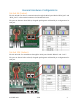
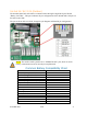
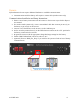
General Hardware Configurations Sol-Ark 8K (Indoor) The Sol-Ark 8K can achieve communications through the RJ-45 ports labeled “RJ45_485” and “RJ45_CAN” or the terminal connectors for RS-485 and CAN. The ports are shown in detail below, alongside pin diagrams and detailed pin configurations for each port. Sol-Ark 12K (Indoor) The Sol-Ark 12K can communicate through the RJ-45 ports labeled “RS-485” and “CAN.
Sol-Ark 5K / 8K / 12K (Outdoor) The Outdoor-Rated Sol-Arks achieve communications through a single RJ-45 port labeled “Battery CAN Bus.” This port combines the pin configurations of the RS-485 and CAN port on the indoor-rated 12K. The port is shown below in detail, alongside a pin diagram and detailed pin configuration. NOTE: The outdoor-rated systems have a “Modbus RS-485” port, which is not for battery communications and is currently not implemented.
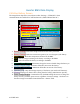
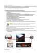
Inverter BMS Data Display CAN Bus Battery Screen The image below depicts the screen shown under “Settings > LI Batt Info” when communications are enabled for CAN Bus batteries (“BMS Lithium Batt 00”). 1. 6. 2. 7. 3. 4. 8. 9. 5. 10. 11. 1. Battery Voltage: Real-time voltage measured at the battery terminals. 2. Battery Current: Real-time current into (positive) or out of (negative) the battery. 3. Battery Temp: Real-time temperature measured at the BMS. 4.
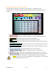
Modbus/RS-485 Battery Screen The image below depicts the screen shown under “Settings > LI Batt Info” when communications are enabled for Modbus/RS-485 batteries (All other “BMS Lithium Batt” modes). 1. 6. 2. 7. 3. 8. 4. 9. 5. 10. 11. 1. 2. 3. 4. 5. Battery Voltage: Real-time voltage measured at the battery terminals. Battery Current: Real-time current into (positive) or out of (negative) the battery. Battery Temp: Real-time temperature measured at the BMS.
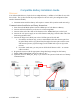
Compatible Battery Installation Guide Discover You will need the Discover Lynk device to adapt the battery’s AEBus to CAN Bus for use with the Sol-Ark. The Lynk will need the proper adapter for the Sol-Ark’s pin configuration (Part number 950-0016-SLRK). • Communications with this battery will require a custom cable (outdoor-rated units only). Communications Installation and Setup Instructions 1. 2. 3. 4. 5. 6. 7. 8. Insert the included RJ45 splitters into the AEBus port of each Discover Battery.
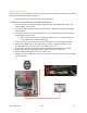
Dyness Dyness Batteries do not require additional hardware to establish communications. • Communications with this battery will require a custom cable (Outdoor units only) Communications Installation and Setup Instructions 1. Ensure correct battery interconnection and connect to the inverter as specified in Dyness’ user manual. 2. For outdoor-rated systems only, create a custom RJ45 cable that connects pin two (2) on the battery to pin six (6) on the inverter. 3.
Blue Ion/eGauge The Sol-Ark will need an eGauge monitoring device, an eGauge USB-485 converter, and a wired internet connection to establish communications with the Blue Ion battery. • You will need a custom RJ45 cable for this setup. Communications Installation and Setup Instructions 1. Connect the Blue Ion to your wired internet connection using the RJ45 port on the back of the unit. 2. Connect the eGauge to a power source. 3.
Blue Ion/Namaka The Sol-Ark will need a Namaka monitoring device and a wired internet connection to establish communications with the Blue Ion battery. • You will not need to make a custom cable for this setup. Communications Installation and Setup Instructions 1. Connect all Blue Ion cabinets together using their “RS-485 Modbus RTU” ports and standard RJ45 ethernet cable. 2. Connect the daisy-chained cabinets to the Namaka’s “BMU” port using standard RJ45 ethernet cable. 3.
Fortress eFlex 5.4 No additional hardware is required to establish communication with the eFlex 5.4. • You will need to make a custom cable for this setup. Communications Installation and Setup Instructions 1. Connect all batteries using the included RJ45 cables. 2. Use the included 120 Ohm termination resistor on either end of the resulting chain. 3.
Fortress eVault & eVault MAX 18.5 No additional hardware is required to establish communication with the Fortress eVault 18.5 battery. • You will need to make a custom cable for this setup. NOTE: The original Fortress eVault can only communicate with the Sol-Ark AFTER a firmware update to the eVault. New eVault units (including the eVault MAX) ship with this update; however, older units may need the latest firmware update.
StorzPower No additional hardware is required to establish communication with StorzPower Resi+ 48V units. • You will need to make a custom cable for this setup. Communications Installation and Setup Instructions 1. Use the DIP switches on the batteries such that the battery to be connected to the inverter is set as slave 1, and each unit behind it increases the slave ID it has. a. Each DIP switch (1-4) represents a bit in the slave ID value. i.e. [1: ON 2: OFF 3: ON 4:ON] = 1101 (binary) = 13 (decimal). 2.
SimpliPhi AmpliPhi No additional hardware is required to establish communication with SimpliPhi AmpliPhi units. • You will not need to make a custom cable for this setup. Communications Installation and Setup Instructions 1. Connect all batteries using the included RJ45 cables, using the two ports nearest each other to bridge the batteries together (GREEN in the picture below). 2. Use the included 120 Ohm terminators on both ends of the resulting chain. 3.
NuEnergy Lithium No additional hardware is needed to establish communications with NuEnergy Lithium batteries. • A custom cable is required to establish communications with the NuEnergy Lithium battery. Communications Installation and Setup Instructions 1. Create a custom cable that connects pins 2, 3, and 4 ONLY (solid orange, white-green, and solid blue) to the battery. 2. Pin two (2) (solid orange) should connect to pin six (6) on the inverter. 3.
NuEnergy Lithium- Power Base M50 No additional hardware is needed to establish communications with NuEnergy Lithium batteries. • A custom cable is required to establish communications with the NuEnergy Lithium battery. Communications Installation and Setup Instructions 1. Create a custom cable that connects pins 6, 7, and 8 ONLY (solid green, white-brown, and solid brown) to the battery. 2. Pin six (6) (solid green) should connect to pin six (6) on the inverter. 3.
PowerSync 51.2V Lithium No additional hardware is required to establish communication with PowerSync 51.2V Lithium batteries. • You will not need to make a custom cable for this setup. Communications Installation and Setup Instructions 1. Set the DIP switches on the battery per the manual and your battery configuration. 2. Connect all batteries with the included short RJ45 cables, connecting each battery via their RS485 ports. 3.
KiloVault HAB No additional hardware is required to establish communications with KiloVault HAB batteries. • You will not need to make a custom cable for setup with a HAB V4, but a custom cable is necessary for HAB V3 or older models. Communications Installation and Setup Instructions 1. Ensure that the batteries are running the latest firmware from KiloVault and that the SolArk communication profile is selected. a. If unsure, contact KiloVault to verify. 2.
Sacred Sun LFP No additional hardware is required to establish communications with Sacred Sun LFP batteries. • You will need to make a custom cable for this setup. Communications Installation and Setup Instructions 1. Use the DIP switches on the batteries such that the battery to be connected to the inverter is set as slave 1, and each unit behind it increases the slave ID it has. a. Each DIP switch (1-4) represents a bit in the slave ID value. i.e.
HomeGrid Stack’d No Additional hardware is required to establish communications with HomeGrid Stack’d batteries. • You will need to make a custom cable for this setup. Communications Installation and Setup Instructions 1. Set the DIP switches on each battery module in a stack. For example, a stack of 5 batteries must have switches set to position 1 through 5. a. Each DIP switch (1-4) represents a bit in the address value. i.e. [1: ON 2: OFF 3: ON 4: ON] = 1101 (binary) = 13 (decimal). 2.
Deka-Duration-DD5300 No additional hardware is needed to establish communications with Deka-DD5300 batteries. • • • Please ensure that you are not wiring to the High Voltage connection terminals of Deka-DD5300 battery. Please refer to the Installation & Operation (I&O) manual of the battery manufacturer and verify the proper communications configuration of CAN bus connections and dip switch settings: A custom cable is required to establish communications with Deka-DD5300 batteries.
PYLONTECH US3000C No additional hardware is required to establish communications with Pylontech US3000C batteries. (Consult Pylontech for other compatible battery modules for communication) • You will need to make a custom cable for this setup. Communications Installation and Setup Instructions 9. Connect all batteries with the RJ45 cable from Link Port 1 to Link Port 0. The first battery with Link Port 0 empty would be the master battery.
PYTES E-BOX-48100R No additional hardware is required to establish communications with PYTES E-BOX-48100R batteries. (Consult PYTES for other compatible battery modules for communication) • You will need to make a custom cable for this setup. Communications Installation and Setup Instructions 19. Connect all batteries with the provided RJ45 cable from Link Port 1 to Link Port 0. The first battery with Link Port 0 empty would be the host battery.
Changelog Notes Revision Changelog Author / Editor Date 1.0 1.1 1.2 1.3 1.4 1.5 1.6 1.7 1.8 1.9 2.0 Initial creation Updated Storz & eFlex information Updated CAN Pinout for Indoor units William Hopkins William Hopkins William Hopkins William Hopkins William Hopkins William Hopkins William Hopkins William Hopkins William Hopkins William Hopkins Bernie D. 1/13/21 2/9/21 2/10/21 2/11/21 3/4/21 4/29/21 5/11/21 7/28/21 8/2/21 10/5/21 10/5/21 William Hopkins/Bernie D.