
Battery Communications Integration Guide


01 JUNE 2022 V 2.6 13
StorzPower
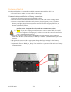
No additional hardware is required to establish communication with StorzPower Resi+ 48V
units.
• You will need to make a custom cable for this setup.
Communications Installation and Setup Instructions
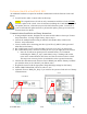
1. Use the DIP switches on the batteries such that the battery to be connected to the inverter
is set as slave 1, and each unit behind it increases the slave ID it has.
a. Each DIP switch (1-4) represents a bit in the slave ID value. i.e. [1: ON 2: OFF 3:
ON 4:ON] = 1101 (binary) = 13 (decimal).
2. Connect all batteries with the RJ45 cable such that they are all in parallel.
3. Create a custom cable that connects pins 1, 2, and 3 only (white-orange, solid orange, and
white-green) to the battery.
4. Pin 1 (white-orange) can be connected to pin one (1) or pin eight (8) on the inverter and
pin 2 (solid orange) can be connected to pin two (2) or pin seven (7) on the inverter.
5. Connect this cable between the battery set as slave one (1) and the inverter’s “Battery
CANBus” (Outdoor models) or “RS-485” (Indoor models) port.
6. Program the inverter with the appropriate charge/discharge settings for this battery.
7. Enable “BMS Lithium Batt” and set its value to “01.”
8. (Optional) Turn on “BMS_Err_Stop” if you wish for the system to fault on loss of battery
communications (This may happen more frequently since the Storz Power batteries do
not feature ground connections).
1 2 3 4 5 6
Inverter Port