
Battery Communications Integration Guide


01 JUNE 2022 V 2.6 20
HomeGrid Stack’d
No Additional hardware is required to establish communications with HomeGrid Stack’d
batteries.
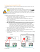
• You will need to make a custom cable for this setup.
Communications Installation and Setup Instructions
1. Set the DIP switches on each battery module in a stack. For example, a stack of 5
batteries must have switches set to position 1 through 5.
a. Each DIP switch (1-4) represents a bit in the address value. i.e. [1: ON 2: OFF 3:
ON 4: ON] = 1101 (binary) = 13 (decimal).
2. Set the DIP switches on the top module of each stack. Standalone stacks and/or the
master of multiple stacks should be set to an address of 1. Subsequent stack top modules
should be set addresses 2, 3, 4, etc…
3. Connect all top modules (if in parallel) together with RJ45 cable between their “Link A”
and “Link B” ports. It does not matter which port is connected to which.
4. Create a custom cable that connects pin four (4) (solid blue), pin five (5) (blue white),
and pin six (6) (solid green) to the same pins on the inverter side. You can also simply
cut the wires for pins one (1), two (2), three (3), seven (7), and eight (8).
5. Connect the cable between the master battery’s top module and the inverter’s “Battery
CANBus” (Outdoor models) or “CAN” (Indoor models) port.
6. Power on the battery units by turning on each module, followed by that stack’s top
module.
7. Program the inverter with the appropriate charge/discharge settings for this battery.
8. Enable “BMS Lithium Batt” and set this value to “00”.
9. (Optional) Turn on “BMS_Err_Stop” if you wish for the system to fault on loss of battery
communications.
10. If communication is still not established, contact HomeGrid to ensure that the unit is on
the latest firmware and configured for communication with Sol-Ark inverters.
11. If error “020” appears on the top module’s LCD screen, check that each battery module’s
dip switches are set correctly and that each battery module is turned on. If the problem
persists contact HomeGrid support.
12. If error “019” appears on the top module’s LCD screen, check that each top module’s dip
switches are set correctly. If the problem persists contact HomeGrid support.
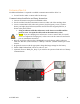
Inverter Port