
Battery Communications Integration Guide

01 JUNE 2022 V 2.6 5
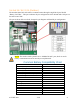
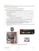
Inverter BMS Data Display
CAN Bus Battery Screen
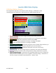
The image below depicts the screen shown under “Settings > LI Batt Info” when
communications are enabled for CAN Bus batteries (“BMS Lithium Batt 00”).
1. Battery Voltage: Real-time voltage measured at the battery terminals.
2. Battery Current: Real-time current into (positive) or out of (negative) the battery.
3. Battery Temp: Real-time temperature measured at the BMS.
4. SOC: State of charge remaining in the battery according to the BMS.
5. SOH: State of health of the battery according to the BMS.
6. Battery Charge Voltage: Maximum voltage the inverter should charge the battery to.
7. Charge Current Limit: Maximum allowable current into the battery.
8. Discharge Current Limit: Maximum allowable current out of the battery.
9. Nominal_Cap: Amp-hour design capacity of the battery (not used on all batteries).
10. Alarms: Displays any alarm codes coming from the battery (manufacturer specific).
11. Force Charge Request: Command sent by the BMS telling the inverter to charge the
battery from any available power source regardless of inverter settings. Not shown on
the above image but would be located below the “Alarms” field.
1.
2.
3.
4.
5.
6.
7.
8.
9.
10.
11.